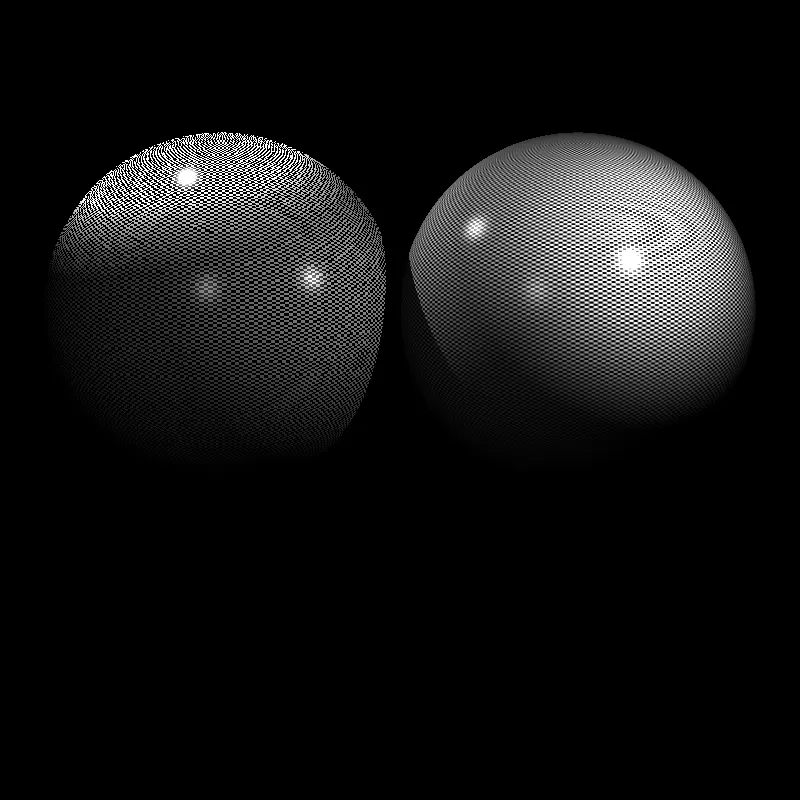
Advanced Ray Tracing : Expansion
Hello everyone! Here is the final part of the Advanced Ray Tracing series : Expansion. There are missing parts until this step. I would like to remind that a quote about destiny from the game Crysis 2, said by Prophet.
No music for this chapter, but proving the African proverb in an opposite way:
If you think you are too small to make a difference, you haven’t spent the night with a mosquito.
In 2011, a Battlefield 3 player performed a glorious kill: the player jumped from the jet, explode enemy jet with an RPG and then jumped again in the jet.
The company awarded the player’s success by adding it to the next Battlefield trailer.
Here we go!
My purpose was simply modeling real life cameras and sensors that may have very distinct parameters that can be customizable or not.
A real life photography camera has 5 controllable parameters:
- Exposure time : controlling the duration of the shutter how much it will stay open (artistically it controls the motion blur effect)
- Aperture : controlling the physical light enters through the lens (artistically it controls the bokeh effect)
- ISO : controlling the light value multiplier to see even darkest scenes (artistically they always say the more ISO the more noise)
- Focal length : controlling the zoom, if the lens enables us to configure zoom (artistically it is chosen for category of subject)
- Focus ring : controlling the focus, generally done by auto focus algorithms (no one even cares, especially the ones who use glasses)
However, diving into the science of creation, transmission and measuring the light energy makes bored a regular photographer. This expansion is for the curious ones.
Some Photonics
Some chemical reaction or movement in a material causes to create or absorb energy. All the calculations will be about energy transferring and turning the energy into another type.
Some things happen in a material (it is heated, go through a chemical reaction, electrons flow inside or surface) and the released energy packets are distributed to the world as photons. The energy of a photon is measured with its frequency. Yes, we have just explored the electromagnetic spectrum. They are just symbolizing the energy of a wave.
Many many photons are emitted with different energy levels (different wavelengths). While some of the emitted ones loitering around into the space, the other ones met with another material. Some of them is absorbed and caused another some chemical or physical thing. Some of them is turned back in different way. And the rest of them runaway between the atoms without being absorbed. First one is absorption, the second one is reflection and the last one is refraction.
We are interested in reflectance until the photon arrives our sensor. Huge number of photon is created and emitted by an “illuminant”. Only some proportion is reflected. Only some of the reflected ones are reflected again. This goes until a few photon arrives our sensor.
The reflectance proportion of a photon per specific wavelength with respect to a specific material is represented as spectral reflectance map of a material.
The Trichromatic Theory (Red, Green, Blue)
Some person/people said that “I can represent any color that I see with 3 primary colors by adjusting their weights.” Some experiments has done (human visual perception, SML cones …)
It is found that high coverage of visible colors can be represented by only 3 primary colors.
Sensor Designs
So that, we have designed our “visible spectrum” sensors according to these 3 primary colors. Some has designed different patterns (BGGR, BGRE etc.) Some has designed different layered structures.
After that, all the collected photons inside a small area (which is pixel) is filtered according to the pattern or layered architecture (notice that we have used refraction concept of the photon movement)
In the end, our collected and filtered photons went into chemical of physical interaction with a material. That material has emitted electrons after the interaction (notice that we have used absorption concept of the photon movement) Like how any material reflects different wavelengths of photons with different proportion, our material absorbs different wavelengths of photons with different proportion and creates emittance of electrons. This is called as quantum efficiency.
Where The Electronics Begin
Previous end is for photonics. This is where the electronics begin. We can’t measure the total energy of photons but total collected charge in capacitors. The circuit that reads the capacitor storage level is named as read out integrated circuit (ROIC). Then the analog signal is created and amplified if needed. Finally it is quantized and presented as n-bits image!
My Design
Get Ahmet Kürşad Şaşmaz’s stories in your inbox
Join Medium for free to get updates from this writer.
As you can guess, not anything is in RGB triplets anymore, but a spectral map. A ray has a spectral map with power (multiplied by coefficients like spectral reflectance coefficient of a material for that specific wavelength) as a return value rather than final RGB values. All the return values of samples are multiplied by exposure time (Implementing a poisson distribution based noise works better, but takes too much execution time! (due to both event counting and accumulating very small precision floating point numbers (which gives the same result again and again (infinite loop)))) Then summed up, if it exceeds the full well capacity (which is the maximum capacity of a capacitor), the value is clamped. Final value is amplified by gain factor, and then quantized.
PS : In order to model depth of field, sample size is calculated according to aperture size. Also, in order to model pixel size (the size of the bucket that collects photons) sample size is calculated according to aperture size.
I couldn’t believe but magically I saw that I have implemented “crop factor” concept without any modification. Changing the sensor size while keeping focal length constant changes field of view. This is a proof that my design is “consistent”!
My Results
It can be seen that my design can model spectral mapping, color filtering arrays, spectral sensors, exposure time & iso & aperture & focal length relations and side effects also.
I have tried to construct Cornell Box with spectral maps. Colors are changing by hue and saturation.
Seeing the same effects with different parameters while I was taking photos of a room with some objects made me proud of myself!


Here we can see the exposure time effect. At every stop, the measured number of photons divided or multiplied by two. Notice that depth of field and noise level stays the same, which is the expected one!


Here we can see the ISO effect. At every stop, the multiplier of the measurement is divided or multiplied by two. Notice that depth of field stays the same. However, we can’t tell the difference of exposure time by our eyes because there is no motion in the scene.


Here we can see the aperture effect. At every stop, the area of the aperture is multiplied or divided by two. So the sample number. Because accumulation is applied to the samples, the more samples the more brightness. Also, we can notice the depth of field effect.


The most crucial part is here. We can validate that the exposure level stays the same while the three components of the exposure triangle changes. This is another proof of constancy. If we can go somewhere in the exposure triangle, we can compansate the exposure level by going the opposite way in the another component.
Thanks for reading.