How to Design Optical Cabling for NVIDIA DGX B300 InfiniBand Clusters

Introduction
Modern AI infrastructure depends on high-speed communication between GPUs, storage systems, and network switches. As distributed training workloads become larger, network bandwidth and physical connectivity become essential considerations in data center design.
The NVIDIA DGX B300 platform is designed for large-scale AI training and inference, combining NVIDIA Blackwell Ultra GPUs with high-speed networking interfaces.
However, deploying DGX B300 systems in a multi-node environment introduces several networking challenges. Engineers must consider compute fabric topology, storage connectivity, optical transceiver selection, fiber types, and overall cabling requirements.
This guide explores the key considerations involved in designing an InfiniBand-based optical cabling architecture for NVIDIA DGX B300 clusters.
Key Takeaways
- DGX B300 supports high-speed cluster networking through ConnectX-8 adapters and BlueField-3 DPUs.
- The compute fabric and storage fabric serve different networking purposes and should be planned independently.
- Quantum-X800 XDR InfiniBand switches provide the switching foundation for high-bandwidth compute networking.
- 800G and 1.6T optical connectivity require careful consideration of lane configuration and optical interfaces.
- MPO fiber selection, polarity, reach, and link budgets are essential parts of deployment planning.
1. NVIDIA DGX B300 Network Interface Overview
The NVIDIA DGX B300 system integrates eight NVIDIA Blackwell Ultra GPUs and high-speed networking interfaces.
According to NVIDIA’s system specifications, its networking configuration includes:

The ConnectX-8 adapters provide the primary high-speed cluster networking interfaces, while BlueField-3 DPUs provide additional networking capabilities for storage and infrastructure services.
In an InfiniBand deployment, the specific assignment of interfaces depends on the selected reference architecture and system configuration.
For this reason, network engineers should distinguish between the physical port configuration supported by the server and the logical network roles defined by the deployment design.
2. Designing the XDR InfiniBand Compute Fabric
The compute fabric is responsible for communication between GPUs distributed across multiple DGX B300 systems.
This includes collective communication operations such as AllReduce, which are fundamental to distributed AI training.
As the number of GPU nodes increases, network topology becomes increasingly important.
2.1 Rail-Optimized Fat-Tree Architecture
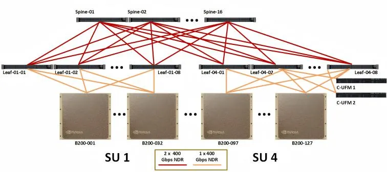
A rail-optimized Fat-Tree architecture provides a structured way to connect GPU nodes and switching layers.
Its primary components include:
Leaf Layer
Leaf switches connect directly to the DGX B300 systems and provide the access layer for GPU cluster communication.
Spine Layer
Spine switches interconnect the Leaf layer and provide scalable communication paths across the cluster.
Inter-Switch Links
High-speed optical connections between Leaf and Spine switches provide the bandwidth required for distributed GPU communication.
The NVIDIA Quantum-X800 XDR InfiniBand platform serves as the switching foundation in the reference compute fabric discussed in this deployment design.
A two-tier switching architecture can provide efficient communication paths while allowing additional Scalable Units to be incorporated into a larger deployment.
2.2 800G and 1.6T Optical Connectivity
High-bandwidth switching architectures require optical interfaces capable of supporting increasing data rates.
In the reference design, 1.6T 2×DR4 OSFP224 optical transceivers are used for selected inter-switch and server-to-switch connectivity configurations.
These optical interfaces combine two 800G DR4 optical channels within a 1.6T module architecture.
When planning these connections, engineers should verify:
- The supported optical interface at both endpoints.
- The number of optical channels and breakout configuration.
- MPO connector type and fiber polarity.
- Single-mode fiber specifications.
- Maximum supported link distance.
- Optical power and insertion-loss budgets.
It is particularly important not to assume that every 1.6T port can be connected using the same cable arrangement. The actual cabling must follow the transceiver’s optical interface specification.
3. Planning MPO Fiber for the Compute Fabric
MPO fiber assemblies are commonly used in high-density data center environments because they allow multiple optical fibers to be managed through a single connector interface.
For the XDR compute fabric described in the reference design, MPO-12 APC single-mode fiber assemblies are specified for the relevant 1.6T 2×DR4 optical links.
The use of MPO-12 connectors helps simplify high-density optical cabling, but connector compatibility alone is not sufficient.
Several details must be checked before deployment.
3.1 Fiber Polarity
MPO polarity determines how transmitting and receiving optical channels are connected between two endpoints.
Incorrect polarity can prevent the optical link from establishing.
Engineers should verify the transceiver manufacturer’s polarity requirements and ensure that the complete link maintains the correct Tx-to-Rx mapping.
3.2 APC Connector Compatibility
MPO-12 APC connectors are used in the reference design.
Get AICPLIGHT’s stories in your inbox
Join Medium for free to get updates from this writer.
APC and UPC connector interfaces should not be treated as interchangeable.
The connector polish, adapter, and transceiver interface must be compatible across the complete optical path.
3.3 Link Loss and Transmission Distance
Fiber attenuation, connector insertion loss, and the number of mating points all influence optical link performance.
A deployment should include an optical loss budget that accounts for the complete channel rather than relying only on the nominal reach of the transceiver.
4. Designing the NDR InfiniBand Storage Fabric
In addition to GPU communication, AI clusters require high-bandwidth access to datasets, model checkpoints, and distributed storage resources.
A separate storage fabric provides a way to organize this traffic independently from the primary compute fabric.
The reference architecture in this guide uses 400G NDR InfiniBand connectivity and NVIDIA Quantum QM9700 switches.
A two-tier Leaf-Spine architecture can be used to connect storage resources and DGX B300 systems.
4.1 400G SR4 Optical Connectivity
For shorter optical links, 400G SR4 transceivers can be paired with multimode fiber assemblies.
The reference design identifies MPO-12 APC multimode fiber for selected links with distances of up to 50 meters.
SR4 connectivity is suitable for short-reach optical applications when the transceiver, fiber grade, connector interface, and link budget are compatible.
4.2 400G DR4 Optical Connectivity
For longer links, 400G DR4 transceivers provide a single-mode optical connectivity option.
The reference design uses MPO-12 APC single-mode fiber for selected links with distances of up to 500 meters.
The actual supported distance must always be checked against the specifications of the selected transceiver and fiber channel.
4.3 SR4 vs. DR4: What Is the Difference?

The choice between SR4 and DR4 should be based on actual transmission distance, existing fiber infrastructure, and equipment compatibility.
5. Estimating Optical Cabling Requirements for Large Clusters
Cabling quantity becomes a major planning factor as the number of GPU systems and switches increases.
The AICPLIGHT reference design describes an eight-Scalable-Unit deployment consisting of:
- 8 Scalable Units.
- 72 DGX B300 systems per Scalable Unit.
- 576 DGX B300 systems in total.
- 4,608 GPUs.
For this reference configuration, the design estimates:

These figures are reference planning estimates, not universal quantities for every DGX B300 deployment.
The final bill of materials should be calculated from the actual number of physical links, transceiver interfaces, fiber assemblies per link, redundancy design, and rack layout.
For large installations, it is also important to reserve additional capacity for maintenance, replacement, and future expansion.
6. Common Cabling Design Considerations
A successful InfiniBand deployment requires more than selecting the correct optical data rate.
Several practical issues should be addressed during the design stage.
Transceiver Compatibility
Verify that the transceiver form factor, optical standard, data rate, and electrical interface are supported by both connected devices.
Fiber Compatibility
Confirm whether the link requires single-mode or multimode fiber, as well as the appropriate fiber grade and connector polish.
Polarity Management
Maintain consistent fiber polarity across all MPO connections and breakout assemblies.
Cable Routing
High-density GPU clusters contain a large number of optical connections. Cable routing should preserve bend radius, reduce congestion, and allow access for maintenance.
Labeling and Documentation
Every connection should be documented with source and destination identifiers, switch port numbers, transceiver types, and cable specifications.
Optical Testing
Perform appropriate inspection, cleaning, and optical loss testing before putting the fabric into production.
Conclusion
Designing optical cabling for NVIDIA DGX B300 InfiniBand clusters requires coordinated planning across compute networking, storage connectivity, switching architecture, and fiber infrastructure.
The combination of Quantum-X800 XDR compute networking and 400G NDR storage connectivity illustrates how different network layers can support the communication requirements of large-scale AI environments.
As GPU clusters continue to expand, optical transceiver selection and MPO fiber planning become increasingly important to deployment reliability and long-term scalability.
For a more detailed look at the reference topology and cabling configurations, see the original AICPLIGHT deployment guide:
NVIDIA DGX B300 Cluster Cabling Design Guide for InfiniBand Networks
Technical references:
- NVIDIA DGX B300 Datasheet: https://resources.nvidia.com/en-us-dgx-software/dgx-b300-datasheet
- NVIDIA DGX B300 User Guide: https://docs.nvidia.com/dgx/dgxb300-user-guide/introduction-to-dgxb300.html