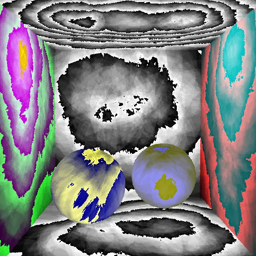
raytracing ( a bit randomized)
This blog post captures the additions to the ray tracer I develop for the course Ceng795 — Advanced Ray Tracing in METU. Previously on this course we have implemented first a raytracer with basic materials/lights and later we have started using acceleration structures to speed up the process along with instancing.
In this homework HW3 we were asked to use distribution raytracing for achieving multiple goals that are listed below:
- Multisampling
- Area Lights
- Depth Of Field
- Motion Blur
- Roughness
Multisampling
In rendering and raytracing, Multisampling solves a crucial problem that is the aliasing. Aliasing occurs in raytracing since a 3D object is nothing but a signal with a lot of parts, and the operation of displaying these 3D signals into our 2D display devices requires sampling. This sampling operation is very simply achieved in raytracing thanks to our rays that are each bein sent from a single pixel, in a sense we are taking a sample from the virtual scene from this pixel using the camera’s current configuration.
However once this sampling is not enough, i.e. scene is under-sampled, many artifacts may occur and the result would not be a good representation of the original shapes.

In the above under-sampled image, the edges of the object are jagged and not smooth. For solving this issue we introduce the multisampling to the scene definition files and send multiple rays for each pixel. I can say that there are mainly two factors that define the quality of a multisampling,
first is the pattern that we chose on pixel surface to send rays and the second is the filtering method for these samples.
For this homework I implemented Jittered-Multisampling with Box Sampling. Jittered pattern tries to avoid the grouping of the rays on one side of the pixel with the smallest cost. It is also called the Stratified Random Sampling.

And the box filter is applied by simply taking the average of these samples for each pixel. This filter is the simplest filter that could be applied and does not provide the most accurate reconstruction of the geometry. However it still gives a remarkable performance when compared to the non-multi-sampled results.

While the result is satisfying to observe, it is important to note that this visual advancement comes with the cost of raytracing time since each pixel sends #samples times more rays.
In my comparisons the releationship between Sample Count and Rendering time was pretty straight forward. Lets say the Scene with no multisampling is rendered in T_1 seconds and the same scene with multisampling is rendered in T_2 seconds where,
T_1 = parsing_time + bvh_building_time + raytracing_time
T_2 = parsing_time + bvh_building_time + n_of_samples * raytracing_time
Depth Of Field
Depth of Field is a common phenomenon that can be observed in camera-shot images of real world.

Until now the images we took from our scenes were taken using a pinhole camera. But for having depth of field we require a camera which has lens-like properties.
In this homework, these lens properties are defined in the scene definition file with aperture-size and focal-distance. Using these properties we sample points on the camera aperture, a square aperture for simplification, and calculate the new ray direction based on the focal plane and our sampled ray origin.
Using this method I was able to generate the following images:


While the effect is visible, the scene to the right seems to be darker and much sharp than the sample output given with the homework;

Roughness
For representing a rough material we deviate the reflection rays using a randomly generated value scaled by the roughness factor of the material. This enables multiple samples to hit object surface and reflect into different directions which simulates the tiny frictions on an objects surface as most objects are not perfectly smooth. As the surface gets rougher the light reflections deviate more and result in blurrier reflections.

Its fascinating how the mirror ball on left feels more like a conductor material now with roughness enabled.
I was able to implement the above features and I was still working on the area lights until my code submission for the HW3. The features below were finalized after the code submission.
Area Lights
Ideally the contribution of an area light to a single hit_point on the object comes from every part of an area light, however with raytracing following such a method would increase the computing cost of the application very fast.
Get Alper Gökcan’s stories in your inbox
Join Medium for free to get updates from this writer.
For this reason we leverage the multisampling of the scene and sample a random point on the area light for each sample, this way the amount of parts on the area light that contribute to the hit_point increases as the sample count increases.
One important addition of area lights is the natural smooth shadows. producing smooth shadows was not possible with point lights since they are the representation of a light source that emits to every direction and is incredibly small compared to its environment.

During implementation of the area lights I encountered multiple bugs.
My initial implementation of the light calculation resulted with the image below:

This result made me think that the contribution of the area lights were calculated negative and once I checked it I saw that my guess was partially true. Their contribution was not only negative, they were -nan, which explaned the completely black results.
After solving the error my image looked like this.

The smooth shadows were nice but the ceiling was not lit by the area light.
Later I found out that I was clamping the contribution of the area light to 0 for negative values, lower_clamp(dot(light_dir, surface_normal), 0).
I changed this to dot(light_dir, surface_normal), but this ofcourse gave some surfaces negative contribution. I actually think the rendered image looks very cool though. ( I suggest checking your monitor’s display options if you are not seeing the negative light on the ceiling, one of my monitors almost fooled me into thinking nothing changed)

And finally I used abs(dot(light_dir, surface_normal)), for making the area light emit on both positive and the negative side of its surface normal.

Motion Blur
Last feature for the homework is the so called motion blur. This phenomenon also occur in real-life camera’s when the object that is being captured moves within the time-frame that the camera’s shutter is open and hence the sensor/film is exposed to light.
While we are not defining a shutter speed for our cameras. We are defining an optional ‘motion vector’ parameter for each object and assume that the object starts this motion at time=0, that is the moment our camera starts receiving light, and ends to its destination at the time=1, which is time moment that our camera stops receiving light.
For simulating this motion we assign a randomly generated time
value, motion_time ∈ [0, 1] to each ray.
However, since recalculating the bvh for each sampled ray is not wise in terms of calculation cost, I alter the bounding box of the object to encapsulate all of its possible bounding boxes during the bvh building phase. And during the bvh traversal, if I hit a bounding box with motion_blur enabled I apply the reverse of the motion defined for this object at time ray.motion_time to the ray.


It can be seen from the result that the sample count increases the smoothness of motion blur since more percentage of the time frame is being captured.
Current Issues
Yes, once I implemented the motion blur I also realized that there was a problem with my dielectrics as they were quite dark and jagged in the inside. I investigated this issue and saw that as the sample amount increases my dielectrics get darker.


Yes, the second problem seems to be that the dielectrics are broken even on their own with no multisampling at all. I must have broke something since HW2.
Noise that is generated on fading parts of area lights, and mostly specular lights.


Lastly the previously mentioned issue that is the inaccurate amount of depth of field effect on the results compared to the sample outputs.
In the next homework we will be focusing on Textures. And I will be working on all the above mentioned issues in the mean time.
See you on the next update…
(*) the image is taken from the lecture slides shared by Professor of the Course, Ahmet Oğuz Akyüz, Ceng795- Multisampling Distribution Raytracing