Quantum Computing, Seen Through the Eyes of an Old IT Guy (Part 5)

Kor Version ← Click!
Reading Python line by line: Bell states and syndrome measurement
Phew… let’s take it slow today.
I’m going to put up a few of the Python code I promised back at the start, and read through them one line at a time.
Like I said, I’m not a programmer, and I’m no Python expert. I’ve just been attacking this brutally hard subject from every angle I could, and reading things through circuit diagrams happened to be what clicked for me.
So that’s how we’ll go, one piece at a time.
The obvious place to start: the Bell state, where things get entangled.
Correlated Bell State (Phi Plus)

Read the circuit, interpret it, then map it against the code!
- Prepare two qubits (q_0, q_1) and two classical bits (everything starts at 0)
- q_0 passes through an H gate and enters superposition
- q_1 passes through a CNOT gate, entangling the two qubits.
If q_0 is 1, flip q_1; if q_0 is 0, do nothing
(= q_0 and q_1 will always hold the same value) - Passing through Measurement (the M box), the phase collapses, the value remains, and it lands in bits 0 and 1
All of that maps onto the code below, one to one.

- 2 qubits, 2 bits:
QuantumCircuit(2, 2) - Superpose q_0:
h(0) - Entangle q_1 with q_0:
cx(0, 1).
cx(control, target), meaning: if the control q_0 is 1, flip the target q_1 - Measure:
measure([0, 1], [0, 1]).
q_0 → c_0, q_1 → c_1
Because the two qubits are entangled, you always get (0,0) or (1,1), each at roughly 50%.
Just like in Part 1: want them to always come out different, (0,1) and (1,0)? Entangle them the opposite way. Let’s look.
Anti-correlated Bell State (Psi Plus)
This started as pure curiosity: if entangled qubits always match, can I make them always differ? Turns out this thing has an official name, and there’s a whole set called The 4 Bell States. (Curiosity keeps opening doors, lol.)
The 4 Bell States are:
Phi+ / Phi-, entangled to match.
Psi+, Psi-, entangled to differ.
The plus and minus are a phase sign difference.
What we built above is Phi+; what we’re building now is Psi+.

- Prepare two qubits (q_0, q_1) and two classical bits (everything starts at 0)
- q_0 passes through H and enters superposition.
q_1 passes through an X gate and flips (q_1 is now 1) - q_1 passes through CNOT, entangling the two.
If q_0 is 1, flip q_1; if q_0 is 0, do nothing
(= q_0 and q_1 will always hold different values) - Through Measurement, the phase collapses, the value remains, stored in bits 0 and 1
Again, this maps onto the code exactly.

- 2 qubits, 2 classical bits:
QuantumCircuit(2, 2) - Superpose q_0:
h(0) - Flip q_1:
x(1) - Entangle:
cx(0, 1).
If the control q_0 is 1, flip the target q_1 - Measure:
measure([0, 1], [0, 1]).
q_0 → c_0, q_1 → c_1
Because the two qubits are entangled through a flip, you always get (0,1) or (1,0), each at roughly 50%.
Get Michael Kim’s stories in your inbox
Join Medium for free to get updates from this writer.
here’s the strange part. Measure Psi+ and Psi-, and you get the same thing. 01 and 10, about 50/50 each.
Different sign, identical result. So the phase doesn’t show up in the computational basis. To see it, you have to rotate the basis (add one more H), and the sign becomes a value you can read.
That’s exactly what the syndrome circuit does next.
Syndrome Measurement = Phase Error Detection
They say phase flip errors are a frequent failure mode in quantum computers.
We just entangled by flipping the value. What if we leave the value alone and flip only the phase?
Catching a flipped phase and restoring it: isn’t that the very starting point of error correction, the foundation of QEC, FTQC, and the Walking Cat? (Maybe not. Just my own take.)
And can’t we connect this to the Ancilla Qubit from earlier, the one doing Error Detection & Correction? Reading the data qubit destroys it, so it read only the Ancilla and pull out the Syndrome. That thing from a few posts back!


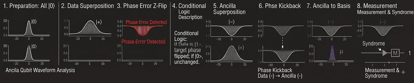
- Prepare two qubits (data, ancilla) and one classical bit (syndrome), all starting at 0
- ‘data’ passes through H and enters superposition (that’s our data qubit)
- ‘data’ passes through a Z gate and its wave’s phase flips to minus (−). (This simulates a phase error hitting the qubit due to noise. If ‘data’ is 1, flip the wave; if ‘data’ is 0, do nothing)
- ‘ancilla’ passes through H and enters superposition
- ‘ancilla’ passes through CNOT, entangling the two (Phase Kickback occurs, flipping the control bit, the ‘ancilla’, to minus)
- ‘ancilla’ passes through H once more
- Only the ‘ancilla’ goes through Measurement.
Its phase collapses and the value lands in ‘syndrome’ (the classical bit)
Reading the result
- Stored value 1 = a phase error (−) occurred on data
- Stored value 0 = no phase error on data, all clear
- We never measured data, so we checked for the error without destroying the data
I drew the wave at each step.

Now let’s check the code against all that!

- 2 qubits (q_data, q_ancilla), 1 classical bit (c_syndrome):
QuantumCircuit(q_data, q_ancilla, c_syndrome).
Same meaning asQuantumCircuit(2, 1), but we named the qubits data and ancilla, and the classical bit syndrome - Superpose q_data:
h(q_data) - Flip q_data’s phase (simulating a Z error):
z(q_data) - Superpose q_ancilla:
h(q_ancilla) - Entangle q_ancilla with q_data (peeking at the error):
cx(q_ancilla, q_data).
If the control q_ancilla is 1, flip the target q_data.
Phase kickback occurs, and the minus (−) left by the error on q_data rubs off onto q_ancilla too.
(The error itself is still sitting on data. This step is detection only; for correction, you’d apply one more Z after detecting) - Superpose q_ancilla again (locking in the error value):
h(q_ancilla) - Measure:
measure(q_ancilla, c_syndrome).
q_ancilla → c_syndrome.
(q_data never enters an M box, so its wave never collapses and the data survives)
Look at the wave drawing alongside it.
At first, superposition, entanglement, phase, waves… none of it would sink in. Now I catch myself throwing these terms around comfortably, and honestly it surprises myself. Working through them one by one gave me my own way of understanding, and drawing abstract ideas like “the phase flipped” as actual waves made everything so much clearer.
There must be people out there wired like me, and I figure some of them will get it through the same route I did.
Drawing the basics as circuit diagrams made them understandable. Checking the diagrams against Python code made them concrete. And rendering that interpretation as values and waves gave me my own personal method of understanding.
The complex algorithms will take more time and effort.
But right now, tonight, I get to end the day feeling pretty good.
Part 6 ← Click!