Restoring a 2001 500Mhz iBook G3 (Dual USB)

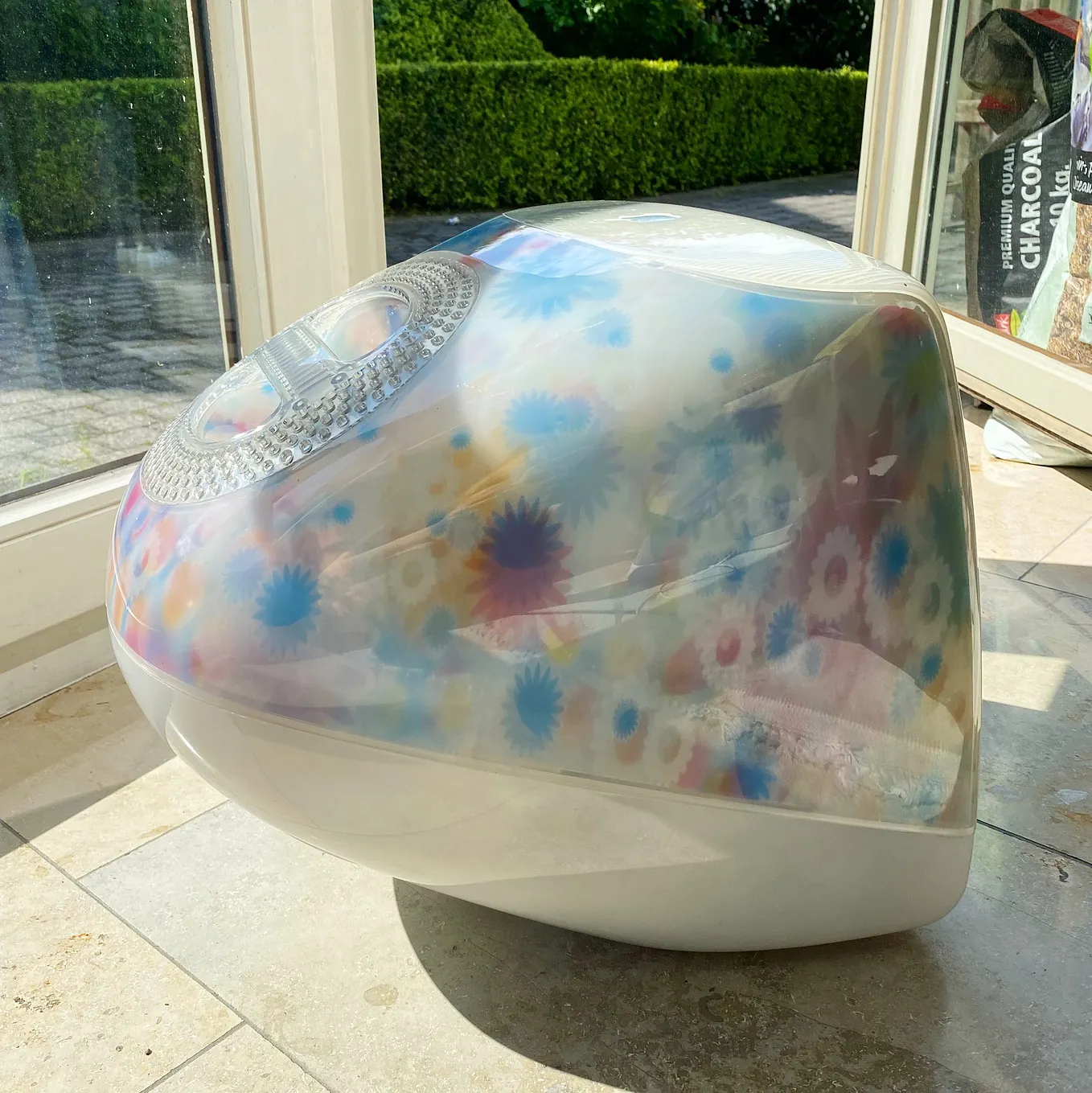
When picking up a second iMac G4 and stumbling upon a flowerpower iMac G3, the friendly seller tossed in an iBook G3. The little machine worked after I purchased a charger on eBay, but had some issues. I put a fresh Tiger installation on the original drive and called it a day. I didn’t really want to invest in the machine, but decided to give it a restore on a budget.
Hardware
Replacing the bottom feet
The rubber feet on the bottom of the machine were missing. Seems like this occurs regularly since a 3D model was available on Thingiverse to print as replacement part.


Rebuilding the battery pack
The battery was obviously dead and I thought it was a great opportunity to try to rebuild a battery pack with 18650 Li-ion cells. I didn’t want to solder directly onto the cell, nor did I feel like building or purchasing a spot welder. Thus I ordered a Liitokala 6-pack with leads.

To ensure reconnecting everything properly, I drew out a diagram of the battery. First physically, but logically as well in case I need to resolve any issues.


Now to test the new batteries performance, they need to be charged.

To test the batteries and re-calibrate the controller I had to drain the battery completely now. Perfect opportunity to run a time-lapse.

Replacing the HDD for an SD card
After a while I figured it would be nice to use the compact machine to try Mac OS 9 and give OpenBSD and Adélie Linux a go on the limited hardware. Having a spare 64Gb MicroSD card, I figured it would be a cheap way to upgrade the machine to more (flash) storage. In combination with an SD to IDE adapter and 3D-printed bracket, I would be able to install the SD card in the ancient computer.


Out with the old

In with the new

Replacing the CCFL backlight with LEDs
The backlight was already behaving a bit sketchy. With the machine turned on, adjusting the display angle could make the backlight flicker or turn off until a next reboot. After replacing the HDD with an SD card, the backlight remained off. I decided with the machine already disassembled and a spare LED kit laying around from replacing the CCFLs on a gutted iMac G4, I would proceed to replace the backlight in this iBook as well. After all, it is possible on a clam-shell G3, how different can it be?

Taking apart the machine took many steps. I had to figure out how to disassemble the LCD panel, but that was only because I didn’t find the right guide at the time.

With some time and patience, I was able to fit the LED-strip inside the LCD panel and route the wire outside the casing. Since the spare driver I had laying around was intended for desktop panels, there was no way that it would fit in the original location. I figured I’d place the driver on the location of the AirPort card or in the reclaimed space by removing the spinning hard drive. Using an external PSU to drive the backlight, all went well.


Next I tried to wire up the driver to the on-board wires for the former CCFL inverter. Without load, the logic board provided 12V, but when wiring up the new backlight, that voltage would drop to about 8V without powering the LED’s. I figured the desktop driver, designed to drive two strips would draw too much power, so I ordered a notebook-specific driver.

Once taken delivery of the new, smaller driver… I realized I could probably install this in the location of the inverter: in the bottom display bezel. There was just no way I would disassemble the display assembly again. Wiring everything up… The result was the same.
Get Bram Beirens’s stories in your inbox
Join Medium for free to get updates from this writer.
My bench PSU told me 0.42A was drawn at 12V. I have no idea how much the CCFL inverter consumed, but I wouldn’t think LED’s were more power-hungry. Experimenting more, the 3.3V enable(?) wire would make the backlight flicker when connected, suspecting a PWM signal coming out of that wire. Additionally, even a simple 0.1A 12V LED strip wouldn’t be powered by that output. I have a suspicion this could be a communication wire and the logic board might only provide the required current ‘on demand’.

Feeling defeated at this point, I wondered what the easiest source would be to get 12V from. Initially the laptop power supply would be a good candidate, but what would the use of an internal display be if it would only work when connected to external power? The battery would be the next candidate! Measuring the pins on the battery connector, I soon found out 12V was available at all times. And sure enough! In my first test set-up, the backlight was lit!

I still had to find a 3.3V output that would only be high when the machine was powered. When looking for a spot to probe the logic board, my eye fell on an unpopulated connector. I was getting lucky, one of the pins went high when the machine is powered. My test set-up is now working. Now I should be able to route the cables and close up the machine.


Easy access in case further debugging is required.
The backlight was dead again and when measuring the pins on the driver board, I found out that the enable pin was shorted to ground! The wire must have been wedged somewhere in the chassis making contact.
Getting used to it now, I took out all the screws again and noticed there was a kink in the enable pin wire. I rerouted the wire and added cushioning on the spot where it could get wedged again.

This time it’s working. The backlight low since I connected the dim pin to the original dim pin. As analyzed by davidg5678 on 68kMLA forums:
It looks like the controller board I bought is set up in the “low-voltage brightest” configuration, but the iBook uses the “high voltage brightest” configuration.
I was aware of this, but figured to wire it up anyway. That way I can at least still control the brightness.
Without OS I haven’t tried sleep mode, but I expect the panel to stay lit. Not sure if modifying the driver board will help this considering the botched job I did getting 12 and 3.3 volts. I don’t have diodes laying around anyway, and the board is easily accessible underneath the keyboard.
In the end, that’s not a big deal to me since I plan to use it mostly for playing around with other PowerPC OS-es on this low-end machine, I won’t mind powering it down after use.
Software
I have a trusty old Late 2009 Mac Mini running OS X Yosemite laying around, which I found perfect to act as a bridge between modern systems and PowerPC systems. The Mini is fast enough to browse some Macintosh-related websites, download the software and either burn it to disk, create a USB disk or transfer over to the older machines over FireWire. I noticed that Yosemite was often able to read and mount certain .toast images that macOS Monteray deemed corrupted.

Installing Mac OS X Tiger 10.4.6
Being most comfortable with Mac OS X and newer, I figured that would be a great place to start with on the new ‘hard-disk’.
First step is to retrieve a copy of the OS. I found the easiest way to install through was through creating a bootable USB disk. Make sure to have your USB drive partitioned using the Apple Partition Map before copying the image over trough Disk utility. After creating the
Booting the iBook from USB requires to boot the machine into Open Firmware (⌘ + ⌥ + O + F). You are greeted with a terminal window in which you’re able to enter commands.
Once into Open Firmware, look for the usb port that has a disk mounted.
dev / ls
boot /pci@f2000000/usb@19/disk@1:3,\System\Library\CoreServices\BootX
Boot the machine by entering the right hardware address of the USB drive and correct partition.

Once in the Mac OS X Installation interface, head over to the Disk Utility through the menu bar Utility options.
Make sure to select the Apple Partition Map on the disk if you want to be able to boot off your drive.
Mac OS Tigers Disk Utility doesn’t allow resizing or creating partitions without erasing the disk, so think about how much space you want to allocate to each OS.
Afterwards you can close Disk Utility and install Mac OS X trough the procedure.

Installing Mac OS 9.1
With plenty of disk space this time, why not install Mac OS 9 as well to experience what the OS was like?
To get the OS 9 installer to boot from USB, a workaround is required. As some form of copy protection, the OS 9 installer refuses to start from re-writable media. The workaround consists of imaging a USB flash drive with a temporary installation of Mac OS 9.2.2, mounting your install disk as read-only and perform the installation trough that temporary installation.
Retrieve a version specifically for your device or a universal image.
Retrieve the Mac OS 9 boot kit and copy the image over to your USB drive.
diskutil list
sudo umount /dev/disk2
sudo dd if=/path/image.toast of=/dev/rdisk2 bs=1m
diskutil eject /dev/disk2
Insert the drive in the computer and boot the machine in Open Firmware mode (⌘ + ⌥ + O + F)
boot usb0/disk@1:,\\:tbxi
Give usb1 a try or ud if usb0 doesn’t work.
Lock the installation image of your choice (File > Get Info, then check the Locked attribute on the bottom/left corner).
Mount the installation image trough Toast 5 Titanium and perform the installation.

Next would be installing Adélie Linux and OpenBSD, but that are adventures for a different time.