How Does a Drone Know Where It Is Pointing?

Every robot lives in two worlds at once:
The world frame and its own body frame.
A robotic arm knows where its joints are relative to itself. But when you ask it to reach for an object on a table, it must answer a harder question:
Where is that object in the world based on what the camera sees?
This problem appears throughout robotics.
The solution is a rotation matrix.

A rotation matrix is the bridge between two coordinate frames.
You build one by asking a simple question:
My axes point somewhere in the world. How can I describe them using the world’s axes?
The answer comes from basic trigonometry.
Start with the drone’s forward axis. This is a unit vector with a length of one. After the drone rotates through a yaw angle, its forward direction can be broken into North and East components using sine and cosine.

The same process gives us the drone’s right-side axis. Its direction also depends on the yaw angle, but one component points in the negative North direction.

During a pure yaw rotation, the drone spins around its vertical axis. The down axis does not change.

Each body axis is now expressed as a unit vector in the world frame.
Get Henry Odoemelem’s stories in your inbox
Join Medium for free to get updates from this writer.
Stack the three vectors as rows, and the result is the yaw rotation matrix.

Now apply the same idea to pitch and roll.
When a quadcopter rotates, its sensors still measure acceleration and angular velocity in the drone’s body frame. However, attitude estimation and navigation often require those measurements to be understood relative to the world.
So we build one rotation matrix for yaw, one for pitch, and one for roll.
Multiply the three matrices together, and the result is a compact 3 × 3 matrix that represents the drone’s complete attitude.

This same principle is used in drones, robotic arms, aircraft, satellites, autonomous vehicles, and many other systems.
The mathematics may look complex at first, but the foundation is simple:
- Represent each axis as a unit vector.
- Resolve it into components using sine and cosine.
- Stack the vectors into a matrix.
- Use the matrix to transform measurements between coordinate frames.
That is where the rotation matrix comes from.
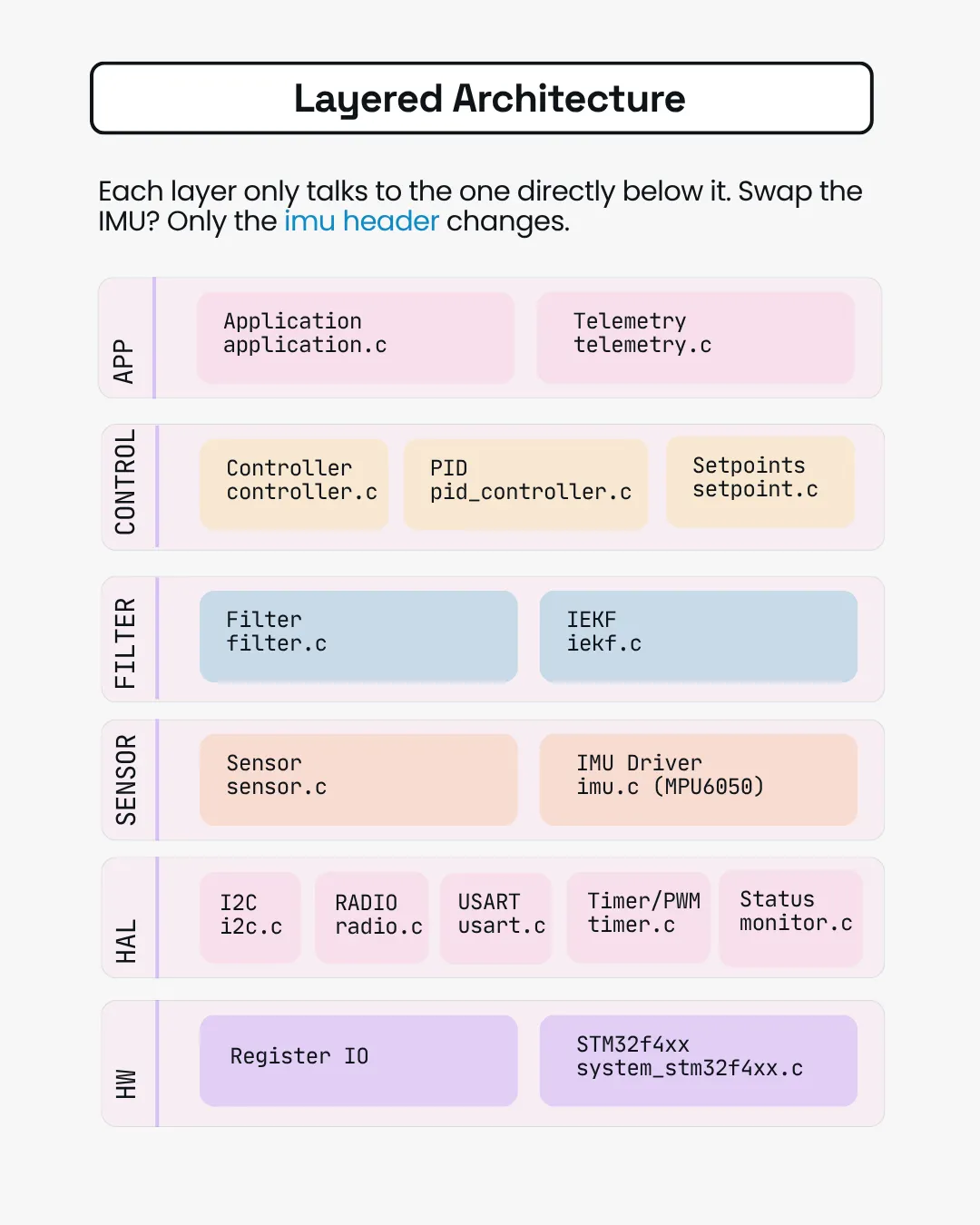
In the QuadFS drone flight controller firmware, this is more than a mathematical exercise. I designed the firmware to use the rotation matrix as part of the attitude-estimation system, allowing the flight controller to determine the drone’s orientation and correctly transform sensor measurements between the body and world frames.
To see how these concepts are implemented in a complete STM32 drone flight controller, follow the free drone build course on YouTube:
https://www.youtube.com/@huobuilds
The firmware, complete course guide, schematics, research materials, and supporting resources are available on Notion.