Demystifying UV Disinfection Terminologies

Over the last few years, have had opportunities to work on projects aimed at water reuse. Any reclaimed water project involves disinfection and over several years now, there has been an uptick in the employment of Ultraviolet (UV) disinfection technology.
At times, as a consultant process engineer, my job is to specify, not design and with UV systems, am mostly doing the former. When I say specify, I mean there are a few process related parameters that I need to provide to the technology supplier (say Trojan or Wedeco) and then in response, I expect the number of UV lamps / modules, banks etc required plus a layout.
Of course, the best technology supplier are specialists, knowledgeable and therefore, they can always provide constructive feedback which helps improve your understanding (eg: “Hey Rajesh, from our experience, for the MBR treated effluent feed to the UV system, the UVT you specified seems to be highly conservative. Based on our experience, we believe 50% is very conservative as you will need more duty units which translates to more CAPEX and power consumption (OPEX) while treating peak flows. Perhaps, 60% is more feasible? But that’s your call to make”)
The above paraphrased feedback is what intrigued me about UV disinfection and gave me an opportunity to learn more about the terminologies associated with the technology.
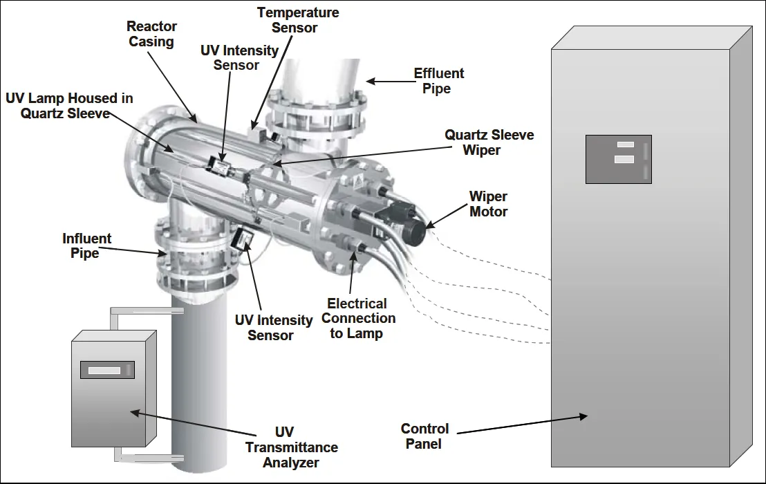
UV Transmittance (UVT) — It is an indication of how much light the water lets through. The higher it is, the further the UV light is able to penetrate. As this parameter has an impact on CAPEX and OPEX, it makes sense to have provision for online monitoring (ie UV transmittance analyser). The transmittance of the quartz sleeve of the UV lamp reduces with time.
If your project does not care about energy consumption (which is unlikely), then you can do without UVT analyser. But this is a key design parameter for the UV disinfection system. In a way, it is an indirect measurement of the UV dose. That’s why, at design stage, where possible, sampling be carried out during dry weather, wet weather, different times of the day and in different seasons to arrive at an optimal UVT value (measured as % per cm).
A key point to remember is that higher operating power of UV lamps translates to higher temperatures and lowered lamp life. When you need higher logs of coliform reduction, the flow must be exposed to the UV intensity for a longer time aka the UV dose is higher (UV dose = Intensity x exposure time).
Of the three mercury based UV lamps, Low Pressure High Output (LPHO) lamps have become popular as they have low power consumption, medium footprint but long lamp life (12–18,000 hours), low fouling rate and have automatic mechanical cleaning system.
In a separate document, I came across some numbers related to UV dose and transmittance that can serve as a guide on your projects:

Another useful document titled Ultraviolet Disinfection Guidance Manual For The Final Long term 2 Enhanced Surface Water Treatment Rule by USEPA had the following numbers for the target pathogen (with emphasis on reducing microbial contamination of drinking water):

Installation Configuration — This is typically either open channel modular design (in conventional WRRFs) or pressurized systems (more common in water reuse applications as they are downstream of membrane treatment applications (eg: Reverse Osmosis) which in turn provides an opportunity to utilize the filtrate pressure / head. There are sub options in the open channel configuration.

UV Intensity Sensor — This is a photosensitive detector usually required to monitor the UV intensity or the UV lamp light output. The UV dose required uses this parameter along with flow rate and UVT. As the UV lamps age, the output and intensity reduce. Lamps must be replaced when intensity drops below a certain value (eg: 20 mW / cm2) or manufacturer recommended run hours. That’s why, monitoring the run hours is a crucial monitoring parameter too.
UV Lamp Aging and Fouling — These factors are accounted for by both the design engineer and the manufacturer. Generally, the fouling factor is multiplied by the aging factor and the range is broadly between 0.4 to 0.9. As per the AWWA F111–25 standard, aging factor is generally 0.85 and shall not exceed 0.9 whereas fouling factor ranges between 0.8 to 0.95.
The fouling factor is defined as the fraction of UV light which passes through a fouled sleeve as compared to a new sleeve. The aging factor is the fraction of UV light emitted from aged UV lamps and sleeves at the end of the specified useful life compared to UV light emitted from new lamps and sleeves.
Lamp Sleeve — This is a quartz tube (that discharges the mercury vapor) that surrounds the UV lamp and protects it. This sleeve can absorb some of the UV light, that can reduce the delivered dose. As the sleeve ages with time, the UV absorption may increase.
Get Rajesh Shenoy’s stories in your inbox
Join Medium for free to get updates from this writer.
Ballast — This is an electrical device that provides the necessary current and voltage required to initiate and maintain UV lamp operation. Simply put, the ballast in a UV module provides power to each UV lamp.
Contact Time (CT) — Flow rate affects the CT. As flowrate increases, the CT reduces and so does the inactivation rate. Peak flowrates are the governing design parameter for UV disinfection. Any short circuiting within the channel / reactor will reduce CT.
UV Banks — This refers to a group of UV modules in a channel / tank.
Germicidal Range — There is a range of UV wavelength that’s responsible for microbial inactivation in wastewater (UVC — 100 to 280nm).
MOC — Metals in contact with the wastewater flow should be corrosion resistant (stainless steel, nickel-copper alloy, bronze or zinc coated steel).
Level Monitoring— Whether it is open type or closed system, level sensors are required. When the level drops to or below minimum level set point (in open systems), or are empty (in closed systems), the UV lamps must be deenergized.
Control System — The automatic control of the UV system is based on on-off, flow paced or dose paced.
In response to changes in wastewater flow, flow pacing is modulating (changing) the power or number of lamps in response.
Dose pacing, considered as more energy efficient, is modulating the power to the UV lamps to achieve the desired dose based on the flow, lamp power, UVT, and UV intensity. However, excessive lamp cycling is not advised as that can reduce the lamp life (in run hours).
Temperature — In general, LPHO and medium pressure UV lamps operate at high temperature. The design is done so as to ensure that sufficient cooling is provided to the lamps via the expected range of design flowrates. To prevent overheating, a temperature switch or sensor is recommended for monitoring. A high temperature set point can trigger an alarm or equipment shutdown.
Information Provided By Parties — After reading the AWWA F111–25 standard, I felt the following table will serve as a useful reference going forward while working on projects with suppliers:

Parameters of Concern — Organic compounds that have not been readily degraded, refractory organic compounds, hardness levels >120 ppm, using ferric chloride as a coagulant to lower phosphorus concentration have interfered with UV disinfection. In the AWWA standard, found this:

The effectiveness of the UV cleaning system is impacted by precipitation and quartz fouling due to iron, calcium, aluminum, magnesium and manganese.
Cleaning System — There are two types: online (automatic) and offline (chemical based).
In the online system, wipers can be used either automatically or manually initiated at prescribed intervals (as per the control system).
In the offline system, for open channel reactors, the UV lamp banks / modules are removed from the channel for cleaning in a separate tank. For the closed UV reactors, they are drained and a cleaning solution is introduced for soaking or there is provision for UV lamp sleeves to be removed and cleaned.
As time goes by, if there are more terminologies or considerations to be added here, will do so.