Full-Stack Flight, Chapter 5: Quadcopter, Part 3: The Flight Controller


This article is part of a 10-part series on how the Centauri Quadcopter was created. For a list of all other articles, please visit the introductory article found here. This article contains Amazon affiliate links. If you make a purchase through them, I may earn a small commission at no extra cost to you.
With the body printed, the hardware assembled, and everything wired up, we’re ready for the software phase: programming the flight controller! Having built both Scout and Centauri, I can confidently say this is the most challenging part of the entire build, but don’t worry, I’ve done it successfully and will walk you through it!
Language of Choice: MicroPython (Python)
As discussed in previous chapters, the Centauri Quadcopter uses an RP2040 microcontroller, hosted on a Raspberry Pi Pico. When developing on the RP2040, we have two directions to choose from in terms of programming language:
- MicroPython: a port of the popular Python programming language, designed specifically for microcontrollers.
- C/C++: a low-level language that is harder to write and implement, but delivers a major boost in raw performance.
For most performance-critical flight controllers (those needing maximum execution speed, sub-millisecond timing precision, low-latency interrupts, and heavy mathematical processing), C/C++ would be the obvious choice. However, my goal with this project was to keep the code and internal processes transparent and approachable for any novice looking to understand flight controllers and build their own. Python is far more approachable, significantly easier to read and understand, and allows for a very quick iterative testing cycle. So for Centauri, as with Scout, I chose to develop the flight controller in MicroPython.
That said, this isn’t without trade-offs. As mentioned above, MicroPython runs significantly slower on the Pico than its C/C++ counterpart because it’s an interpreted language. Flight controllers notoriously need to run code very quickly, and MicroPython’s slower execution puts that at risk. Even so, I’ve successfully developed the Centauri Flight Controller in MicroPython with ample performance for stable flight; I assure you, it’s do-able!
The Centauri Flight Controller: What it is, What it isn’t
Within the domain of quadcopter flight controllers and computers, there are what I’d call four “levels” of flight control, which I’ll describe below.

- Rate Control: the most primitive form of flight controller. It only monitors and controls angular velocity (the rate of change in orientation). If the pilot lifts off the sticks, the flight controller tries to achieve zero change in orientation, holding whatever orientation it’s currently in.
- Attitude Control: one level up from rate control. This is more complex: the flight controller not only observes and controls the rate of change in orientation, but also its absolute orientation: its pitch and roll angle relative to the ground. If the pilot lifts off the sticks, the flight controller tries to “level out” the quadcopter, achieving 0 degrees of pitch and roll.
- Position Control: one level up from attitude control. Here we move beyond a mere “flight controller” and into “flight computer” territory. At this level, the flight computer also observes the position of the quadcopter in 3D space, typically using multiple sensors like a GPS and barometer. It observes and optimizes for a fixed position in space: a location, altitude, and orientation. If the pilot lifts off the sticks, the flight computer holds that position, actively adjusting if wind pushes it off course.
- Mission Control: the highest level of flight computer, typically reserved for industrial and professional applications beyond the scope of hobbyist drones. Here, an even more sophisticated flight computer updates the quadcopter’s goal position over a planned period of time (a flight mission), autonomously flying it through space to accomplish a goal. This is common in professional applications like agriculture (seeding a field along a fixed flight path). Another example is DJI’s “return to home” feature, where the drone takes over autonomous control and flies itself back to a set point on autopilot.
The Centauri Flight Controller is a “Rate Control” flight controller. It’s the most primitive form, requiring only the limited avionics system we’ve given it (read more about that in the previous chapter).
When I sat down to create Centauri in July of 2025, my original intent was an Attitude Control flight controller, capable of observing and controlling its attitude (pitch and roll angles). I later abandoned that in pursuit of something simpler, but you’ll still find remnants of it in today’s flight controller code (like the angle estimation algorithms)!
How the Centauri Flight Controller Works
For the sake of organization, I’ll describe the flight controller as having “two sides,” each covered in detail in the sections below.
The first is the startup sequence: everything the flight controller does to prepare for normal operation the moment it boots (as soon as the Raspberry Pi Pico receives power).
The second is the control loop: the core loop that continuously and rapidly performs all normal operation, both in flight and when grounded.

The graphic above depicts the high-level architecture of the Centauri Flight Controller, split into its two “phases.” I’ll describe each step in detail in the sections below, alongside some code snippets!
If you’d like to follow along with the entire flight controller code as you read, you can find it here!
Before we dive into the code, I want to mention that its style likely won’t match the traditional Python “best practices” you may have read about or seen online. I keep traditional abstraction layers like modules, classes, and functions to a minimum, and my use of math, slicing, and the like is decidedly “not normal.” There’s a reason for all of this: performance. I’ll elaborate at the end of this chapter, but wanted to give you a heads-up here.
And with that, let’s take a closer look at the flight controller code.
Boot Sequence: LED On
Upon booting, the very first thing the flight controller does is turn on the Raspberry Pi Pico’s onboard LED.
import machine

# First thing is first: set up onboard LED, turn it on while loading
print("Turning LED on...")
led = machine.Pin("LED", machine.Pin.OUT)
led.on()
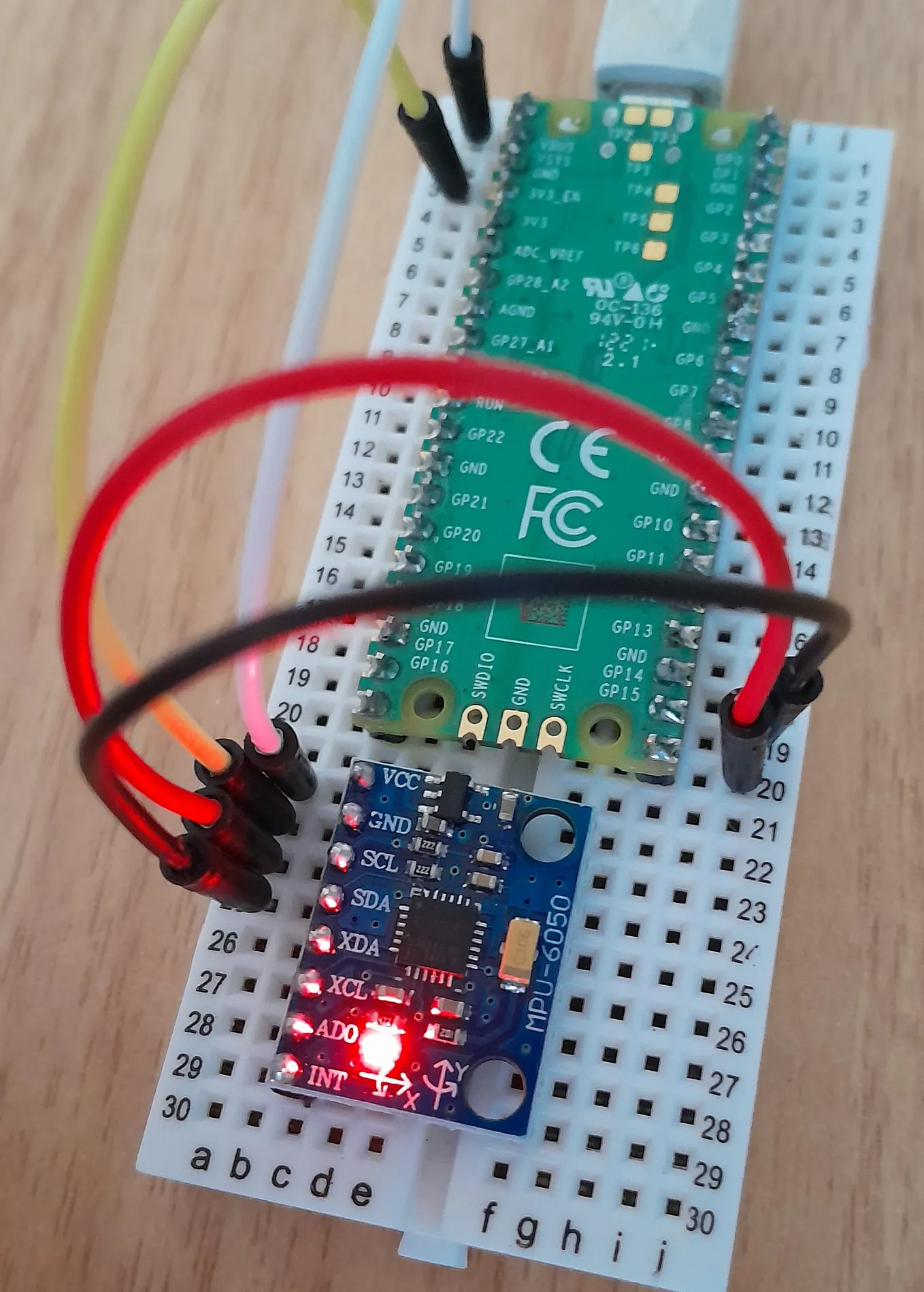
As shown in the image above, the Raspberry Pi Pico has a small onboard LED that can be controlled by code. I turn it on simply to confirm that power has successfully reached the Pico and the flight controller code is now running.
Boot Sequence: Initialize Motor PWM Control
The next step in the boot sequence is immediately initializing the pulse width modulation (PWM) signal for each of the four motors.
We prioritize doing this right away for two reasons:
- ESC timeout: The ESCs were likely powered on the moment the Pico was. Some ESCs have a “timeout”: if they don’t receive a PWM signal within several seconds of booting, they switch back off.
- Safety: the propellers and motors are the only moving parts on the quadcopter, and an unexpected spin-up is a real safety concern. It’s best practice to immediately set the motors to 0% throttle when power is received, in case a “leftover” PWM signal lingered on the Pico from a prior boot.
gpio_motor1:int = 21 # front left, clockwise
gpio_motor2:int = 20 # front right, counter clockwise
gpio_motor3:int = 19 # rear left, counter clockwise
gpio_motor4:int = 18 # rear right, clockwise
target_hz:int = 250 # the number of times to run the PID loop
M1:machine.PWM = machine.PWM(machine.Pin(gpio_motor1), freq=target_hz, duty_ns=1000000)
M2:machine.PWM = machine.PWM(machine.Pin(gpio_motor2), freq=target_hz, duty_ns=1000000)
M3:machine.PWM = machine.PWM(machine.Pin(gpio_motor3), freq=target_hz, duty_ns=1000000)
M4:machine.PWM = machine.PWM(machine.Pin(gpio_motor4), freq=target_hz, duty_ns=1000000)
I’ll elaborate on two things in the code snippet above:
freq: you'll notice the freq parameter is set to 250 on each motor PWM. This is the frequency of the PWM signal in hertz: how many complete on/off cycles occur per second. At 250 Hz, each cycle lasts exactly 4 ms. We use 250 Hz because our control loop (the "PID loop") runs at 250 Hz, so we may update the throttle as often as 250 times per second.
duty_ns: you'll notice duty_ns is set to 1000000. This value is 1,000,000 nanoseconds, the width of the PWM signal. In the world of ESCs, a pulse width of 1,000,000 ns represents 0% throttle, while 2,000,000 ns represents 100% throttle. So by initializing each motor's pulse width at 1,000,000 nanoseconds, we start each at 0% throttle.

The graphic above depicts this, showing the pulse width changing to represent different throttle levels. 0% throttle lasts 1 ms and 100% throttle lasts 2 ms, with linear scaling between the two.
Boot Sequence: Wireless Transceiver Setup
As discussed in the previous chapter, an HC-12 serves as the wireless transceiver that lets the quadcopter communicate bidirectionally with the pilot. Setting up and configuring the HC-12 early is a priority so the quadcopter can immediately send out an “I’m online” message, confirming it has booted successfully and is operational.
The HC-12 uses the UART protocol to communicate with the Pico, so in MicroPython we can leverage the UART class from the machine module to interface with it. The HC-12 also has a "SET" pin that lets the Pico switch between configuration and communication mode, which we set up as well.
print("Setting up HC-12 via UART...")
hc12_set = machine.Pin(7, machine.Pin.OUT) # the SET pin, used for going into and out of AT mode
uart_hc12 = machine.UART(1, tx=machine.Pin(8), rx=machine.Pin(9), baudrate=9600)
uart_hc12.read(uart_hc12.any()) # clear out any RX buffer that may exist
After initializing the UART object we need to communicate with the HC-12, we “pulse” it to confirm it’s hooked up and working. The HC-12 accepts a range of “AT Commands” when the SET pin is pulled low (configuration mode); one is simply sending AT, to which it responds OK to confirm it's on and operational.
# pulse HC-12
hc12_set.low() # pull it LOW to enter AT command mode
time.sleep(0.2) # wait a moment for AT mode to be entered
hc12_pulsed:bool = False
hc12_pulse_attempts:int = 0
hc12_pulse_rx_buffer:bytearray = bytearray()
while hc12_pulsed == False and hc12_pulse_attempts < 3:
    print("Sending pulse attempt # " + str(hc12_pulse_attempts + 1) + "...")
    uart_hc12.write("AT\r\n".encode()) # send AT command
    hc12_pulse_attempts = hc12_pulse_attempts + 1
    time.sleep(0.2) # wait a moment for it to be responded to

    # if there is data
    if uart_hc12.any():
        hc12_pulse_rx_buffer.extend(uart_hc12.read(uart_hc12.any())) # append
        if "OK\r\n".encode() in hc12_pulse_rx_buffer:
            hc12_pulsed = True
            print("Pulse received!")
            break
        else:
            print("Data received back from HC-12 but it wasn't an OK (pulse)")
    else:
        print("No data received from HC-12.")

    # wait
    time.sleep(1.0)

# handle results of HC-12 pulse attempt
if hc12_pulsed:
    print("HC-12 pulsed! It is connected and working properly.")
else:
    print("HC-12 did not pulse back! Ensure it is connected, in baudrate 9600 mode, and working properly.")
    FATAL_ERROR()
Communicating with the pilot via the HC-12 is a vital capability, so if establishing a connection with the module fails, the quadcopter enters a failure mode, flashing a code on the Pico’s onboard LED and refusing to continue.
Once we confirm the HC-12 is set up and operational, we make a few configurations. For the HC-12 on the quadcopter to communicate with the HC-12 on the pilot’s transmitter, the two must be configured identically.
We place the HC-12 into FU3 mode, its “general purpose” mode, which provides a good trade-off between range and speed:
# Configure HC-12 while still in AT mode: mode = FU3
print("Setting HC-12 mode to FU3...")
uart_hc12.write("AT+FU3\r\n".encode()) # go into mode FU3 (normal mode)
time.sleep(0.2) # wait a moment
response:bytes = uart_hc12.read(uart_hc12.any())
if "OK+FU3\r\n".encode() in response:
    print("HC-12 in FU3 mode successful!")
else:
    print("HC-12 not confirmed to be in FU3 mode!")
    FATAL_ERROR()
We then configure it to listen and broadcast on channel 2, one of 100 selectable channels:
# Configure HC-12 while still in AT mode: channel = 2
print("Setting HC-12 channel to 2...")
uart_hc12.write("AT+C002\r\n".encode())
time.sleep(0.2) # wait a moment
response:bytes = uart_hc12.read(uart_hc12.any())
if "OK+C002\r\n".encode() in response:
    print("HC-12 set to channel 2!")
else:
    print("HC-12 not confirmed to be in channel 2.")
    FATAL_ERROR()
And finally, we set its broadcasting power (when it sends data) to the maximum level of 8, which equates to 20 dBm:
# Configure HC-12 while still in AT mode: power
print("Setting HC-12 power to maximum level of 8...")
uart_hc12.write("AT+P8\r\n".encode())
time.sleep(0.2) # wait a moment
response:bytes = uart_hc12.read(uart_hc12.any())
if "OK+P8\r\n".encode() in response:
    print("HC-12 power set to level 8 (20 dBM)")
else:
    print("Unsuccessful in setting HC-12 power level to 8.")
    FATAL_ERROR()
After making those configurations, we return the “SET” pin to a high state, bringing the HC-12 back to its normal operating mode (out of configuration mode):
# now that the HC-12 is set up and configured, close out of AT mode by setting the SET pin back to HIGH
print("Returning HC-12 SET pin to HIGH (exiting AT mode)...")
hc12_set.high()
time.sleep(0.5) # wait a moment for the HC-12 to successfully get out of AT mode before proceeding with sending any messages
You’ll notice that just after HC-12 setup completes, the first thing it does is send out a “HC12 OK” message, so the pilot can see the quadcopter is powered on and capable of communicating through a working HC-12 unit. This is the special packet discussed in Full-Stack Flight, Chapter 2: Defining a Communication Protocol, which can carry a plain-text, unstructured message.
# define special message packet function for sending special packets
print("Defining special message function...")
def send_special(msg:str) -> None:
    ToSend:bytearray = bytearray()
    ToSend.append(0b00000001) # append header byte with bit 0 = 1 to identify it as a special packet
    if len(msg) > 50:
        msg = msg[0:50] # limit to 50 chars
    ToSend.extend(msg.encode())
    ToSend.extend("\r\n".encode()) # terminator
    uart_hc12.write(ToSend)

# send online notification
print("Sending 'HC12 OK' message...")
send_special("HC12 OK")
Note: I previously put together a helper class for working with the HC-12, which you can find here. I’m not using it in the Centauri Flight Controller, for performance reasons. If you’d like to learn more about how the HC-12 works, I suggest reading through it and possibly the HC-12 manual.
Boot Sequence: IMU Setup & Calibration
With wireless communication now set up, we move on to the onboard Inertial Measurement Unit (IMU). As mentioned in the previous chapter, Centauri uses the common and affordable MPU-6050 as its IMU. As you’ll see later, the IMU is another vital part of the quadcopter’s avionics; without it, flight would never happen!
The MPU-6050 uses the I2C protocol, which MicroPython supports via the I2C class of the machine module.
We initialize the I2C interface and then perform a scan to check available devices on the bus:
# Confirm MPU-6050 is connected via I2C
print("Setting up I2C...")
i2c = machine.I2C(0, sda=machine.Pin(16), scl=machine.Pin(17))
if 0x68 not in i2c.scan():
    print("MPU-6050 not connected via I2C!")
    FATAL_ERROR("MPU-6050 not connected!")
else:
    print("MPU-6050 confirmed to be connected via I2C.")
Now that we’ve confirmed it is showing up, we run a quick check of its “whoami” register, which should always respond with the same value, 0x68, confirming it's present and operating:
# Confirm MPU-6050 is on and operational by reading the "whoami" register
print("Reading MPU-6050 WHOAMI register...")
whoami:int = i2c.readfrom_mem(0x68, 0x75, 1)[0]
if whoami == 0x68:
    print("MPU-6050 WHOAMI passed!")
    send_special("IMU OK")
else:
    print("MPU-6050 WHOAMI Failed!")
    FATAL_ERROR("MPU6050 WHOAMI Fail")
Next, we write a few values to various registers on the MPU-6050 to wake it up and configure it. I won’t go into detail here to save space (this alone could fill a full chapter), but I’m sure you could feed this snippet to your favorite AI agent and get a very verbose explanation. 😊
# Set up MPU-6050
print("Waking up MPU-6050...")
i2c.writeto_mem(0x68, 0x6B, bytes([0])) # wake up
print("Setting MPU-6050 gyro scale range to 1,000 d/s...")
i2c.writeto_mem(0x68, 0x1B, bytes([0x10])) # set full scale range of gyro to 1,000 degrees per second
print("Setting MPU-6050 accelerometer scale range to 8g...")
i2c.writeto_mem(0x68, 0x1C, bytes([0x10])) # set full scale range of accelerometer to 8g
print("Setting MPU-6050 LPF to 10 Hz...")
i2c.writeto_mem(0x68, 0x1A, bytes([0x05])) # set low pass filter for both gyro and accel to 10 hz (level 5 out of 6 in smoothing)
After that, we “read back” those registers to confirm the configuration updates took effect (not shown here).
With communication established and the MPU-6050 configured correctly, we’re ready to calibrate it. No IMU is perfect; every one has some error or “drift.” When the MPU-6050 sits absolutely still, it still returns minor values across its gyroscope and accelerometer readouts that aren’t actually true; they’re the result of small imperfections. Later, in the control loop, we’ll want readings as accurate as possible. To achieve that, we observe these values for a few seconds now so we know what to subtract from the raw readings later.
The following snippet collects hundreds of readings across a three-second span:
# Perform IMU (Gyro & Accel) Calibration
gfs:int = 0          # g-force samples (sum)
gxs:int = 0          # gyro x samples (sum)
gys:int = 0          # gyro y samples (sum)
gzs:int = 0          # gyro z samples (sum)
samples:int = 0      # to count the number of samples we collect
for i in range(3):
    print("Beginning IMU calibration in " + str(3 - i) + "... ")
    time.sleep(1.0)
send_special("IMU Cal...")
print("Calibrating IMU...")
started_at_ticks_ms:int = time.ticks_ms()
while time.ticks_diff(time.ticks_ms(), started_at_ticks_ms) < 3000: # 3 seconds

    # Read
    gyro_data:bytes = i2c.readfrom_mem(0x68, 0x43, 6)    # read 6 gyro bytes, 2 for each axis
    accel_data:bytes = i2c.readfrom_mem(0x68, 0x3B, 6)   # read 6 accelerometer bytes, 2 for each axis

    # Transform gyro data
    gyro_x = (gyro_data[0] << 8) | gyro_data[1]
    gyro_y = (gyro_data[2] << 8) | gyro_data[3]
    gyro_z = (gyro_data[4] << 8) | gyro_data[5]
    if gyro_x >= 32768: gyro_x = ((65535 - gyro_x) + 1) * -1 # convert unsigned ints to signed ints (so there can be negatives)
    if gyro_y >= 32768: gyro_y = ((65535 - gyro_y) + 1) * -1 # convert unsigned ints to signed ints (so there can be negatives)
    if gyro_z >= 32768: gyro_z = ((65535 - gyro_z) + 1) * -1 # convert unsigned ints to signed ints (so there can be negatives)
    gyro_x = gyro_x * 10000 // 328      # now, divide by the scale factor to get the actual degrees per second. Multiply by 10,000 to both offset the divisor being 328 (not 32.8 as specified for this gyro scale) AND ensure the output is 1000x more so we can do integer math
    gyro_y = gyro_y * 10000 // 328      # now, divide by the scale factor to get the actual degrees per second. Multiply by 10,000 to both offset the divisor being 328 (not 32.8 as specified for this gyro scale) AND ensure the output is 1000x more so we can do integer math
    gyro_z = gyro_z * 10000 // 328      # now, divide by the scale factor to get the actual degrees per second. Multiply by 10,000 to both offset the divisor being 328 (not 32.8 as specified for this gyro scale) AND ensure the output is 1000x more so we can do integer math

    # Transform accel data
    accel_x = (accel_data[0] << 8) | accel_data[1]
    accel_y = (accel_data[2] << 8) | accel_data[3]
    accel_z = (accel_data[4] << 8) | accel_data[5]
    if accel_x >= 32768: accel_x = ((65535 - accel_x) + 1) * -1 # convert unsigned ints to signed ints (so there can be negatives)
    if accel_y >= 32768: accel_y = ((65535 - accel_y) + 1) * -1 # convert unsigned ints to signed ints (so there can be negatives)
    if accel_z >= 32768: accel_z = ((65535 - accel_z) + 1) * -1 # convert unsigned ints to signed ints (so there can be negatives)
    accel_x = (accel_x * 1000) // 4096 # divide by scale factor for 8g range to get value. But before doing so, multiply by 1,000 because we will work with larger number to do integer math (faster) instead of floating point math (slow and memory leak)
    accel_y = (accel_y * 1000) // 4096 # divide by scale factor for 8g range to get value. But before doing so, multiply by 1,000 because we will work with larger number to do integer math (faster) instead of floating point math (slow and memory leak)
    accel_z = (accel_z * 1000) // 4096 # divide by scale factor for 8g range to get value. But before doing so, multiply by 1,000 because we will work with larger number to do integer math (faster) instead of floating point math (slow and memory leak)

    # use accel data to calculate current G-Force
    gforce:int = tools.isqrt(accel_x*accel_x + accel_y*accel_y + accel_z*accel_z)         # 1,000 would be 1g

    # increment
    gxs = gxs + gyro_x
    gys = gys + gyro_y
    gzs = gzs + gyro_z
    gfs = gfs + gforce
    samples = samples + 1

    # wait
    time.sleep(0.01)
With those readings collected, we can calculate the inherent biases on each of the gyroscope’s axes:
# calculate biases
print(str(samples) + " IMU samples collected.")
gyro_bias_x:int = gxs // samples
gyro_bias_y:int = gys // samples
gyro_bias_z:int = gzs // samples
gforce_bias:int = (gfs // samples) - 1000     # the "bias" can be described as the difference between 1 full g and the avg reading. So if, being totally still, the IMU is reading 0.9g, we know it is off by 0.1g, because it should be 1.0g standing still!
print("Gyro Bias: " + str(gyro_bias_x) + ", " + str(gyro_bias_y) + ", " + str(gyro_bias_z))
print("GForce Bias: " + str(gforce_bias))
send_special("IMU Calib OK")
We’ll later use these to get a better estimate of the actual changes in angular velocity by subtracting this error from the readings!
Note: for this to work, the quadcopter must rest absolutely still during this three-second period. As soon as you power it on, step away and don’t touch it for the first ~10 seconds to ensure an accurate calibration reading!
Boot Sequence: Other Things
I won’t detail the other things that happen during the boot sequence, since I only wanted to cover the “big ones” above. The rest is primarily setting up variables and bytearray objects that get reused later in the control loop (to save memory), along with some precomputed calculations, timestamp flags, and the like. You're welcome to look through it in the source code yourself!
Get Tim Hanewich’s stories in your inbox
Join Medium for free to get updates from this writer.
Now, with the Centauri flight controller booted up, set up, and ready, it transitions to the control loop, and that is where flight happens!
Control Loop: Mark Loop Start Time
The first thing that happens within the control loop is marking the current time:
# mark loop start time
loop_begin_us:int = time.ticks_us() # ticks, in microseconds (us)
The reason is to maintain a fixed and consistent 250 Hz control loop. As you’ll see at the end of the loop, if there’s excess time (i.e. it finished before the 4 ms needed for 250 Hz), it waits out the remainder before proceeding, ensuring consistent timing.
Control Loop: Receive Control Input
Next, it receives new control input via the HC-12. This involves checking whether any newly received data is available to read on the UART interface, and if so, reading and processing it.
bytesavailable:int = uart_hc12.any()
if bytesavailable > 0:
    # read into the rxBuffer (just a place to read them into)
    bytesread:int = uart_hc12.readinto(rxBuffer, bytesavailable)

    # Do we have room to move all of the newly received bytes into the process buffer?
    # if the available space remaining is NOT ENOUGH to fit ALL of the newly received data... dump it!
    if (len(ProcessBuffer) - ProcessBufferOccupied) < bytesread:
        ProcessBufferOccupied = 0 # set the count for how much space is occupied to 0 so it just begins rewriting from the beginning.

    # copy the bytes we just received in the rxBuffer into the ProcessBuffer, byte by byte (one by one)
    for i in range(0, bytesread):
        ProcessBuffer[ProcessBufferOccupied + i] = rxBuffer[i]

    # increment how much of the ProcessBuffer is now occupied
    ProcessBufferOccupied = ProcessBufferOccupied + bytesread

# Step 2: Do we have a complete line to work with (a "\r\n" terminator is there)
while True: # continuously search until there are no more left
    TerminatorLoc:int = ProcessBuffer.find(terminator, 0, ProcessBufferOccupied)
    if TerminatorLoc == -1: # if a terminator (\r\n) was not found...
        break # break out of the while loop
    else:

        # Process the line
        if ProcessBuffer.startswith(TIMHPING): # PING: simple check of life.
            uart_hc12.write(TIMHPONG) # PONG back
        elif ProcessBuffer[0] & 0b00000001 == 0: # if bit 0 is 0, it is a control packet
            unpack_successful:bool = tools.unpack_control_packet(ProcessBuffer, control_input)
            if unpack_successful:
                input_throttle_uint16 = control_input[0]
                input_pitch_int16 = control_input[1]
                input_roll_int16 = control_input[2]
                input_yaw_int16 = control_input[3]
                control_input_last_received_ticks_ms = time.ticks_ms() # mark that we just now got control input
        elif ProcessBuffer[0] & 0b00000001 != 0: # if bit 0 is 1, it is a settings update
            settings:dict = tools.unpack_settings_update(ProcessBuffer)
            if settings != None:
                pitch_kp = settings["pitch_kp"]
                pitch_ki = settings["pitch_ki"]
                pitch_kd = settings["pitch_kd"]
                roll_kp = settings["roll_kp"]
                roll_ki = settings["roll_ki"]
                roll_kd = settings["roll_kd"]
                yaw_kp = settings["yaw_kp"]
                yaw_ki = settings["yaw_ki"]
                yaw_kd = settings["yaw_kd"]
                i_limit = settings["i_limit"]
                send_special("SETUPOK") # send special packet "SETUPOK", short for "Settings Update OK".
            else:
                print("It was settings but it failed.")
        else: # unknown packet
            print("Unknown data received via HC-12")
            send_special("?") # respond with a simple question mark

        # Move the conveyer belt back so the new unprocessed data is right at the beginning
        NewDataStarts:int = TerminatorLoc + 2
        NumberOfBytesToMove:int = ProcessBufferOccupied - NewDataStarts
        ProcessBufferMV[0:NumberOfBytesToMove] = ProcessBufferMV[NewDataStarts:NewDataStarts + NumberOfBytesToMove]
        ProcessBufferOccupied = ProcessBufferOccupied - NewDataStarts
If you’re at all familiar with reading incoming binary data from UART, you might think to yourself, “can’t all of this be done in one line?”
And you wouldn’t be entirely wrong! MicroPython’s UART class has a read() function that hands you whatever data is available on the line. So why not just use that and skip all this reading into a buffer, the memoryview slicing, and so on?
The answer is performance. Every call to UART.read() allocates a new bytes object. That additional memory allocation will eventually, within a few loops, push memory to a critical mass and trigger MicroPython's garbage collector to clear the heap, and that takes time! Precious time! In a normal Python project, a 200 ms pause for garbage collection goes unnoticed. But here, we must maintain a fixed 250 Hz control loop, so the entire process has to complete within 4 ms. Our time budget is tiny and we can't afford garbage collection, so we must avoid allocating new memory each loop.
In the code above, you’ll see the handling of the three types of packets the quadcopter may receive from the pilot’s transmitter (revisit chapter 2 for a deeper look):
- PING: a simple “ping” message: the pilot’s transmitter asking “are you there?”, encoded as
TIMHPINGin ASCII. The quadcopter respondsTIMHPONGto confirm "yes, I'm here." - Control Packet: the transmitter sending updated control input: new throttle, pitch, roll, and yaw values. The packet is unpacked and the input variables are updated (more on this later).
- Settings Packet: the transmitter sending updated flight settings (PID gains). The packet is unpacked and the onboard PID gains are updated.
Control Loop: Read IMU
With any new control input from the pilot received and recorded, we move on to a crucial part: observing the quadcopter’s physical change in orientation by reading the IMU.
We do this by using I2C to read from specific registers on the MPU-6050:
i2c.readfrom_mem_into(0x68, 0x43, gyro_data) # read 6 bytes, 2 for each axis for gyro data
i2c.readfrom_mem_into(0x68, 0x3B, accel_data) # read 6 bytes, 2 for each axis for accel data
We just captured a total of 12 bytes of data from the MPU-6050:
- 6 bytes from the Gyroscope (2 for X axis, 2 for Y axis, 2 for Z axis)
- 6 bytes from the Accelerometer (2 for X axis, 2 for Y axis, 2 for Z axis)
We now perform a minor transformation on those bytes to reconcile them into the actual measurement readings we need:
# Process & Transform raw Gyroscope data
gyro_x = (gyro_data[0] << 8) | gyro_data[1]
gyro_y = (gyro_data[2] << 8) | gyro_data[3]
gyro_z = (gyro_data[4] << 8) | gyro_data[5]
if gyro_x >= 32768: gyro_x = ((65535 - gyro_x) + 1) * -1
if gyro_y >= 32768: gyro_y = ((65535 - gyro_y) + 1) * -1
if gyro_z >= 32768: gyro_z = ((65535 - gyro_z) + 1) * -1
roll_rate = gyro_x * 10000 // 328
pitch_rate = gyro_y * 10000 // 328
yaw_rate = gyro_z * 10000 // 328
I know that looks complicated! For the sake of brevity, I won’t dive too deep, but here are a few notes on what’s happening:
- The two bytes per axis are combined via bitwise operations into a single larger number.
- That number, ranging from 0 to 65,535 (an unsigned
uint16), is converted to range from -32,768 to 32,767 (a signedint16). - That raw value is converted to degrees per second by dividing by
328.
If you want to understand how we arrived at the 328 value in #3, see the comments for this section in the actual flight controller code.
And now we have the actual degrees-per-second reading from the IMU’s gyroscope! One last step: subtract out the bias we calculated earlier during the IMU calibration phase (during the boot sequence):
pitch_rate = pitch_rate - gyro_bias_y
roll_rate = roll_rate - gyro_bias_x
yaw_rate = yaw_rate - gyro_bias_z
Control Loop: PID Calculations
Now for the PID calculation, which determines exactly what each of the four motor throttles should be.
In the PID loop, we compare the pilot’s desired rate of orientation change with the actual rate of orientation change. There will be a difference, and the PID calculation determines how to correct it by varying thrust across the four motors.
In a previous step we collected the control input from the pilot; we now convert it into a desired pitch, roll, and yaw rate:
# convert the desired pitch, roll, and yaw from (-32,768 to 32,767) into (-90 to +90) degrees per second
# Multiply by 90,000 because we will interpret each as -90 d/s to +90 d/s
# We are multplying by 90,000 instead of 90 here so we can keep it in units of 1,000 and do integer math instead of floating point math
desired_pitch_rate:int = (input_pitch_int16 * 90000) // 32767
desired_roll_rate:int = (input_roll_int16 * 90000) // 32767
desired_yaw_rate:int = (input_yaw_int16 * 90000) // 32767
We then use these values to calculate the error on each axis (the difference between goal and actual):
# error = desired - actual
error_pitch_rate:int = desired_pitch_rate - pitch_rate
error_roll_rate:int = desired_roll_rate - roll_rate
error_yaw_rate:int = desired_yaw_rate - yaw_rate
Now, with the error values for all three axes, we can perform the PID calculation. I won’t do a deep dive into how PID controllers work, but in essence there are three “forces” that each contribute to how much effort is applied to close a gap: the proportional, integral, and derivative forces. Each can be tuned independently, with the combination of all three applied together to close the gap. The PID calculation for the pitch axis is shown below:
# Pitch PID calculation
pitch_p:int = (error_pitch_rate * pitch_kp) // PID_SCALING_FACTOR
pitch_i:int = pitch_last_i + ((error_pitch_rate * pitch_ki) // PID_SCALING_FACTOR)
if pitch_i < -i_limit: # constrain within I limit. I originally was using min(max()) here but that takes 210 us. Way too slow. Doing it this way uses only 40 us.
    pitch_i = -i_limit
elif pitch_i > i_limit:
    pitch_i = i_limit
pitch_d = (pitch_kd * (error_pitch_rate - pitch_last_error)) // PID_SCALING_FACTOR
pitch_pid = pitch_p + pitch_i + pitch_d
Now we have pitch_p, pitch_i, and pitch_d, which we combine at the end into pitch_pid, all three terms together. pitch_pid is important because we use it to calculate each motor's throttle level to resolve the "errors." I'm not showing the calculations for roll and yaw, but they work exactly the same way.
Finally, to calculate the pulse width of each of the four motor signals, we put everything together:
# Calculate the mean pulse width the PWM signals will use
mean_pwm_pw:int = 1_000_000 + ((input_throttle_uint16 * 10_000) // 65535) * 100

# calculate throttle values for each motor using those PID influences
m1_pwm_pw = mean_pwm_pw + pitch_pid + roll_pid - yaw_pid
m2_pwm_pw = mean_pwm_pw + pitch_pid - roll_pid + yaw_pid
m3_pwm_pw = mean_pwm_pw - pitch_pid + roll_pid + yaw_pid
m4_pwm_pw = mean_pwm_pw - pitch_pid - roll_pid - yaw_pid
Above, we first calculate the “mean” pulse width from the throttle input (think of it as a percentage of the range between 1,000,000 ns and 2,000,000 ns). We then apply the combined PID influences for each of the three axes in a pattern reflecting each motor’s position and thrust orientation on the airframe.
Control Loop: Update Throttle Signal
Now we have the pulse width for each of the four motors, representing its throttle level, ready to send to the ESCs!
But before sending these directly to the ESCs, we put a few safety filters in place.
First, we constrain the pulse widths to between 1,000,000 ns and 2,000,000 ns (the min/max values the ESCs recognize), in case the math pushed them below or above that range:
# takes ~60 us
# you may think why not just use the min/max functions here - I originally was! But those are very slow, taking ~440 us to min/max all four. Saving a lot of time doing it manually like this.
if m1_pwm_pw < 1000000:
    m1_pwm_pw = 1000000
elif m1_pwm_pw > 2000000:
    m1_pwm_pw = 2000000
if m2_pwm_pw < 1000000:
    m2_pwm_pw = 1000000
elif m2_pwm_pw > 2000000:
    m2_pwm_pw = 2000000
if m3_pwm_pw < 1000000:
    m3_pwm_pw = 1000000
elif m3_pwm_pw > 2000000:
    m3_pwm_pw = 2000000
if m4_pwm_pw < 1000000:
    m4_pwm_pw = 1000000
elif m4_pwm_pw > 2000000:
    m4_pwm_pw = 2000000
Second, we check for “red flag” scenarios that, for safety reasons, immediately shut the motors down entirely, even if the PID calculation says otherwise:
# MOTOR SHUTDOWN CONDITIONS (safety)
if input_throttle_uint16 == 0 or time.ticks_diff(time.ticks_ms(), control_input_last_received_ticks_ms) > 2000:

    # shut off all motors
    # 1,000,000 nanoseconds = 1 ms, the minumum throttle for an ESC (0% throttle, so no rotation)
    m1_pwm_pw = 1000000
    m2_pwm_pw = 1000000
    m3_pwm_pw = 1000000
    m4_pwm_pw = 1000000

    # reset cumulative PID values (I and D related)
    pitch_last_i = 0
    roll_last_i = 0
    yaw_last_i = 0
    pitch_last_error = 0
    roll_last_error = 0
    yaw_last_error = 0
The code above detects two “red flag” situations and shuts off the motors if either occurs:
- Pilot’s throttle is at 0%: this may seem obvious: if the pilot’s input is 0%, how could the motor throttles be anything but 0%? Keep in mind the PID loop is always running. Even if the pilot isn’t touching the controls, the flight controller is actively trying to maintain orientation, so if you pick the quadcopter up and move it, the motors may spin up to compensate. This check prevents that.
- 2+ seconds since control input was last received: while flying, the quadcopter risks wandering out of range of the pilot’s transmitter. Unable to receive new inputs to reduce throttle or shut down, the flight controller would keep acting on the pilot’s most recent input, leading to an out-of-control quadcopter, which is VERY dangerous. To mitigate this, the logic above shuts the motors down entirely if no new control input has been received for 2 seconds or more.
After passing through those two “red flag” filters and making any necessary adjustments, we’re ready to update the throttle signal for each of the four ESCs!
# adjust throttles on PWMs
M1.duty_ns(m1_pwm_pw)
M2.duty_ns(m2_pwm_pw)
M3.duty_ns(m3_pwm_pw)
M4.duty_ns(m4_pwm_pw)
Control Loop: Record & Stream Telemetry
After adjusting the motor thrusts by updating the pulse width fed to each ESC, the control loop checks whether it’s time to record or stream telemetry.
The first thing this section does is check whether it’s time to record again. It does so by checking whether the time elapsed since telemetry was last recorded now exceeds the interval between recordings:
if time.ticks_diff(time.ticks_ms(), telemetry_last_recorded_ticks_ms) >= record_telemetry_every_ms: # proceed to store a snapshot if it is timeIf it’s time to record new telemetry, it packs all the values to be recorded: current battery voltage, the pitch/roll/yaw rates, current G-force level, current control input, and more:
# first, get a ADC reading
vbat_u16:int = vbat_adc.read_u16() # read the value on the ADC pin, as a uint16 (0-65535)

# Using the ADC reading, estimate the actual supply voltage
vbat:int = ((-248_065 + (vbat_u16 * 297)) + 50_000) // 100_000 # results in a value between 60 and 168 (6.0 and 16.8 volts respectively)

# Prepare input values to packet as expected: rates
packable_pitch_rate:int = pitch_rate // 1000
packable_roll_rate:int = roll_rate // 1000
packable_yaw_rate:int = yaw_rate // 1000

# Prepare input values to packet as expected: angles
packable_pitch_angle:int = pitch_angle
packable_roll_angle:int = roll_angle

# Prepare input values to packet as expected: gforce
packable_gforce:int = (gforce + 50) // 100

# prepare input values as expected: input values
packable_input_throttle:int = (input_throttle_uint16 * 100) // 65535
packable_input_pitch:int = ((((input_pitch_int16 + 32768) * 100) // 65535) * 2) - 100
packable_input_roll:int = ((((input_roll_int16 + 32768) * 100) // 65535) * 2) - 100
packable_input_yaw:int = ((((input_yaw_int16 + 32768) * 100) // 65535) * 2) - 100

# Prepare input values as expected: motor throttles
packable_m1_throttle:int = (m1_pwm_pw - 1000000) // 10000
packable_m2_throttle:int = (m2_pwm_pw - 1000000) // 10000
packable_m3_throttle:int = (m3_pwm_pw - 1000000) // 10000
packable_m4_throttle:int = (m4_pwm_pw - 1000000) // 10000

# prepare packet last received ago
lrecv_ago_ms:int = time.ticks_diff(time.ticks_ms(), control_input_last_received_ticks_ms)
I won’t describe the snippet above line by line, but if you’re interested, I highly encourage you to visit this section (lines 693–737) in the source code, where I left verbose comments explaining each line!
After collecting all the values, it then packs them using the pack_telemetry function of the tools module:
tools.pack_telemetry(time.ticks_ms(), vbat, packable_pitch_rate, packable_roll_rate, packable_yaw_rate, packable_pitch_angle, packable_roll_angle, packable_gforce, packable_input_throttle, packable_input_pitch, packable_input_roll, packable_input_yaw, packable_m1_throttle, packable_m2_throttle, packable_m3_throttle, packable_m4_throttle, lrecv_ago_ms, telemetry_packet_store)The line above packs the telemetry into the pre-defined telemetry_packet_store bytearray (intentionally not allocating new memory for a new object).
We now have a bytearray containing an encoded snapshot of telemetry; great! To record it, we do not immediately write to the Raspberry Pi Pico's flash storage; that would take too long given the tight timing of a flight controller. Instead, we write it to a temporary memory buffer that collects a series of these while in flight (much faster), and later, when not flying, the actual "flush" to flash storage happens.
# Record it by adding it to the temporary memory buffer we have going while in flight
if (temp_telemetry_storage_len - temp_telemetry_storage_used) > len(telemetry_packet_store): # if we have enough room for another telemetry packet store.
    for i in range(len(telemetry_packet_store)): # manually copy telemetry packet via loop.
        temp_telemetry_storage[temp_telemetry_storage_used + i] = telemetry_packet_store[i]
    temp_telemetry_storage_used = temp_telemetry_storage_used + len(telemetry_packet_store) # increment how many bytes are now used.
The snippet above checks whether there’s enough room in the buffer to copy this snapshot in. If so, it copies it over byte by byte. We’re not using slicing here, as that allocates new memory and takes too long; believe it or not, I’ve found the byte-by-byte copy via the for loop is faster and more efficient.
Now we’ve “recorded” (saved to a temporary buffer) telemetry that will eventually reach the Pico’s onboard flash storage. But as described in previous chapters, I also wanted the Centauri quadcopter to transmit telemetry back to the pilot while operating, keeping them updated on its status. After recording with the snippets above, we transmit using the snippet below:
# if we also have the opportunity to send telemetry right now, send it
# We only send under 2 conditions:
# 1. We are unarmed (throttle = 0)
# 2. It is due time!
if input_throttle_uint16 == 0: # if we are unarmed (throttle is 0%), we will consider streaming some telemetry periodically to the controller. It is important to only send data via HC-12 while unarmed because the HC-12 is half duplex, meaning it can't send and receive at the same time. Full focus should be put into receiving input commands while armed.
    if time.ticks_diff(time.ticks_ms(), status_last_sent_ticks_ms) >= 1000: # send via HC-12 to controller every 1000 ms (1 time per second)

        # construct stream packet
        # we just packed all the data into the record buffer
        # so pull out the telemetry we will send from there directly
        telemetry_packet_stream[0] = 0b00000000                     # header byte. Bit 0 = 0 means it is a status packet.
        telemetry_packet_stream[1] = telemetry_packet_store[3]      # vbat
        telemetry_packet_stream[2] = telemetry_packet_store[4]      # pitch rate
        telemetry_packet_stream[3] = telemetry_packet_store[5]      # roll rate
        telemetry_packet_stream[4] = telemetry_packet_store[6]      # yaw rate
        telemetry_packet_stream[5] = telemetry_packet_store[7]      # pitch angle
        telemetry_packet_stream[6] = telemetry_packet_store[8]      # roll angle
        telemetry_packet_stream[7] = 13                             # \r
        telemetry_packet_stream[8] = 10                             # \n

        # send
        uart_hc12.write(telemetry_packet_stream) # no need to append \r\n to it because the bytearray packet already has it at the end!
        status_last_sent_ticks_ms = time.ticks_ms() # update last sent time
You’ll see above that telemetry is only transmitted via the HC-12 when throttle is at 0% (we are NOT flying, NOT armed). I do this because the HC-12 is a half-duplex transceiver, not a full-duplex one, meaning it can only send or receive at any given moment, never both at once. If the pilot’s transmitter broadcasts an important message while the drone is transmitting its own, the pilot’s message will not be received. That’s detrimental during flight, where low latency is critical; missing an updated control packet, even for a fraction of a second, could cause a crash.
Once throttle is confirmed at 0% and status telemetry hasn’t been broadcast for at least 1 full second, the stream packet is “constructed” by copying over the leading bytes from the full-sized telemetry packet we recorded earlier: just the critical data the pilot cares about, such as battery. Again, slicing would be simpler here, but it allocates a new object, which costs memory and drags down performance. After copying, it sends the data by writing to the HC-12’s UART interface!
Finally, the temporarily recorded telemetry data (in the large buffer) is “flushed” (saved) to local file storage:
if input_throttle_uint16 == 0: # if we are unarmed
    if temp_telemetry_storage_used > 0: # if we have some telemetry to write

        # flush to flash storage
        # takes ~40,000 us, uses ~2,496 bytes of new memory
        log = open("log", "ab")
        for i in range(temp_telemetry_storage_used):
            if free_bytes > 0: # if we have free bytes in capacity
                log.write(bytes([temp_telemetry_storage[i]]))
                free_bytes = free_bytes - 1 # decrement the number of bytes that are now free
        log.close()

        # clear out the temporary storage bytearray
        # takes ~259,000 us, uses 0 bytes of new memory
        for i in range(temp_telemetry_storage_len):
            temp_telemetry_storage[i] = 0
        temp_telemetry_storage_used = 0 # reset used counter
It checks two conditions: throttle is at 0% (we’re not flying, so timing isn’t critical right now) and there is data to flush. If both pass, it flushes to local storage.
You’ll notice in the comments above that this is a very time-consuming process: at roughly 300 ms, it most certainly breaks the timing of the control loop. But that’s acceptable here because this does NOT happen during active flight. It only runs when throttle is at 0%, meaning a timing-tight control loop (PID loop) isn’t necessary.
Control Loop: Wait Excess Time
The final task in the control loop is to wait… to do nothing! As described above, the Centauri control loop runs at 250 Hz, or 250 times per second. That means each loop must execute consistently every 4 ms, no more, no less.
In testing the control loop timing, I found that execution time varies but is usually around 2.5 ms. To ensure the loop runs consistently every 4 ms, we check how far along we are in the 4 ms window and wait out any gap between the elapsed time and the required 4 ms:
# Wait if there is excess time
excess_us:int = cycle_time_us - time.ticks_diff(time.ticks_us(), loop_begin_us) # calculate how much excess time we have to kill until it is time for the next loop
if excess_us > 0:
    time.sleep_us(excess_us)
Close

We’ve now covered arguably the most challenging part of the entire Centauri ecosystem! We designed and printed the airframe in chapter 3, added and wired up the hardware in chapter 4, and have now programmed the flight controller firmware here in chapter 5!
The Centauri quadcopter is now complete! Next, we’ll move on to the other half of the duo: the Pilot’s Transmitter, the device the pilot uses to control the quadcopter in flight.
Click here to continue reading in this series: Full-Stack Flight, Chapter 6: Transmitter, Part 1: Transceiver Platform.
Read to start building? Join the Full Stack Flight Discord to ask questions, share progress, and connect with other makers building their own version of Centauri!