Build RTK on ESP32-S3 (PART 3) microcontroller and modem programming + NTRIP correction


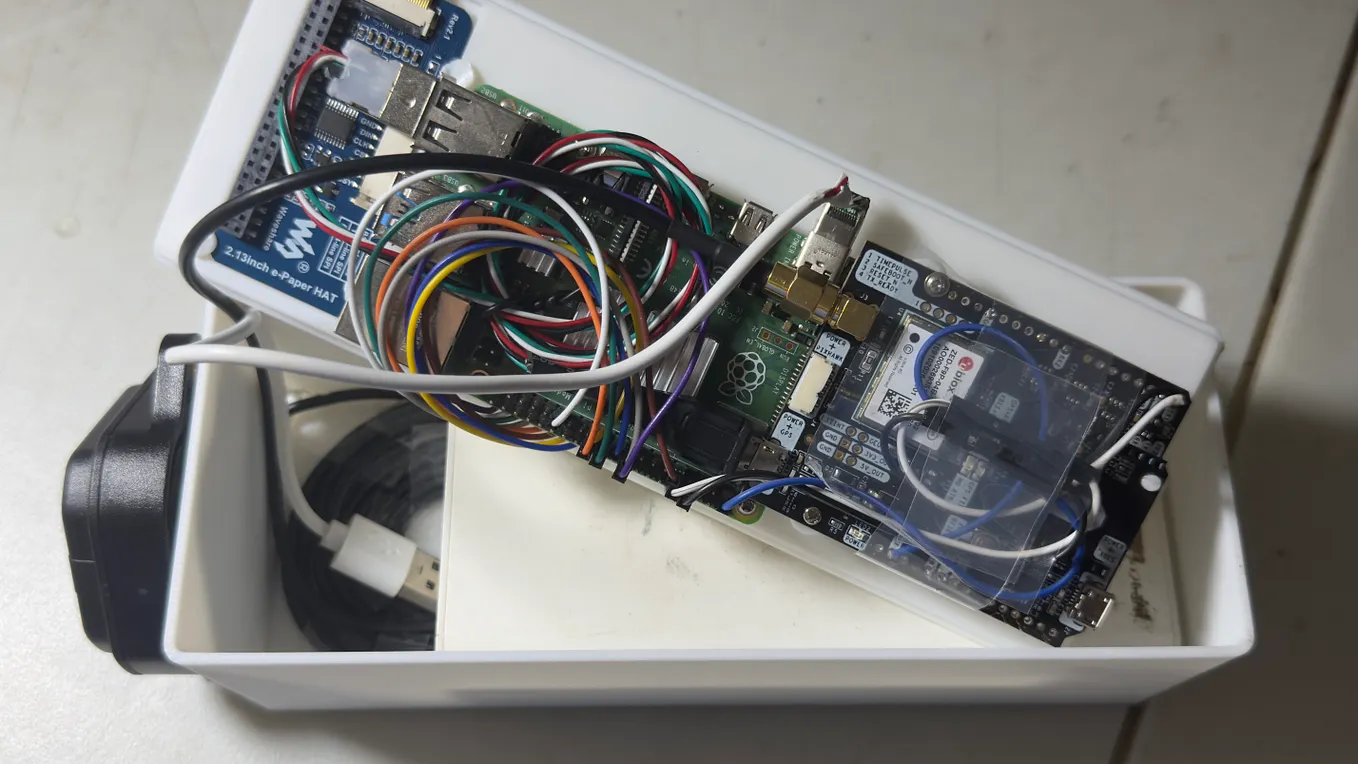
In the previous stages of this project, I connected a u-blox ZED-F9P GNSS receiver and an e-ink display to an ESP32-S3.
Receiving normal GPS coordinates was relatively straightforward. The difficult part was turning those meter-level coordinates into centimeter-level RTK positions while the tracker was moving and connected only through a cellular modem.
In this part, I will cover:
- Programming the SIM7670G modem directly with AT commands
- Registering a global IoT SIM on a roaming LTE network
- Opening a cellular data session
- Connecting to an NTRIP caster
- Sending the rover’s GGA position to the caster
- Receiving binary RTCM corrections
- Forwarding those corrections to the ZED-F9P
- Detecting RTK Float and RTK Fixed states
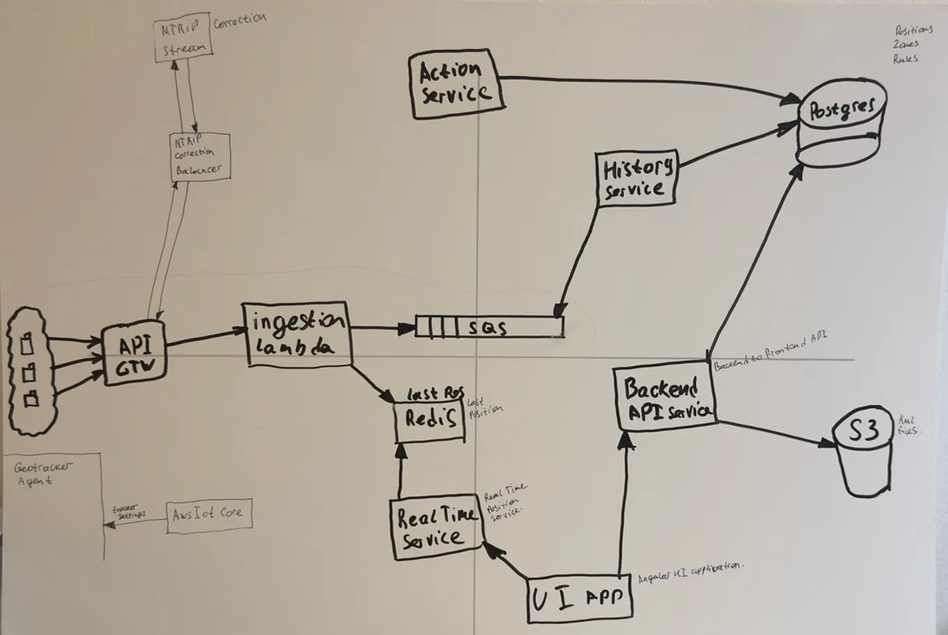
- Publishing the resulting position to AWS IoT Core
Hardware used
My prototype uses:
- LilyGO T-SIM7670G-S3 Standard
- ESP32-S3
- Integrated SIMCom SIM7670G LTE modem
- u-blox ZED-F9P RTK receiver
- 1NCE cellular IoT SIM
- LTE antenna
- Multi-band GNSS antenna
- Waveshare 2.13-inch e-ink display
- RTKdata NTRIP correction service
The ESP32-S3 is the bridge between the internet and the GNSS receiver.
It sends the current approximate position to the NTRIP caster, receives RTCM correction bytes through the modem, and forwards those bytes unchanged to the ZED-F9P.
Starting the SIM7670G correctly
A cellular modem is not just another serial peripheral. It has its own processor, firmware, power state, SIM interface and network state.
The LilyGO board requires a specific power-key sequence. For the Standard board, I use a short pulse to start the modem. After that, the firmware repeatedly sends AT until the modem responds. Do not assume that waiting a fixed number of seconds means the modem is ready. Check for an actual response.
The official LilyGO repository contains board-specific examples and modem initialization sequences for the T-SIM7670G family. It is a much safer starting point than a generic ESP32 modem tutorial: LilyGO Modem Series.
Waiting for the SIM
Once the modem responds, I disable command echo and enable detailed errors. The modem may temporarily report SIM failure immediately after boot. I allow a few attempts, but I do not retry indefinitely.
A persistent SIM failure normally indicates one of these problems:
- SIM inserted incorrectly
- Incompatible SIM size or adapter
- Poor SIM-contact pressure
- Modem firmware problem
- Power instability
- Damaged board or SIM interface
Software cannot repair a physically disconnected SIM.
Configuring the 1NCE APN
My 1NCE SIM uses this APN: sensor.net
I configure PDP context 1 before registration: AT+CGDCONT=1,"IP","sensor.net"
I then read the configuration back: AT+CGDCONT?
Verifying the setting matters. An OK response only means the command was accepted; reading it back confirms that the expected context is present.
Letting the SIM select a roaming network
A global IoT SIM should not be permanently locked to the operator visible during development.
I use automatic operator selection: AT+COPS=0
Registration is monitored with: AT+CEREG?
For a 1NCE SIM, status 5 is normally a successful result: +CEREG: 2,5,290D,015EFD0A,7
My modem eventually reported: [INFO] LTE registration: registered while roaming (5)
+CPSI: LTE,Online,310-410,...
+COPS: 0,2,"310410",7
A temporary +CSQ: 99,99 while the modem is searching does not necessarily indicate a hardware failure. It means the signal value is not currently known.
Get Yatsiv Petro’s stories in your inbox
Join Medium for free to get updates from this writer.
The important design decision was to avoid blocking startup while waiting for LTE. The application keeps running GNSS and display processing while a timed state machine checks registration periodically.
What NTRIP does
NTRIP is commonly used to transport GNSS correction data over the internet.
Our rover performs four steps:
- Open a TCP connection to the NTRIP caster.
- Send an HTTP-like request containing the mountpoint and credentials.
- Periodically send the rover’s valid GGA position.
- Receive binary RTCM correction messages and forward them to the ZED-F9P.
Sending a valid GGA position
The AUTO mountpoint needs to know where the rover is located.
The ZED-F9P emits a GGA sentence such as: $GNGGA,144921.00,3259.4386,N,08000.2396,W,1,12,0.75,4.5,M,...
Before sending it to the caster, I verify:
- The NMEA checksum is correct
- Latitude is present
- Longitude is present
- The fix-quality field is not zero
The GGA position should be sent periodically so the caster can continue selecting the appropriate correction source as the rover moves.
Receiving RTCM without corrupting it
The ESP32 first checks how many bytes are waiting: AT+CIPRXGET=4,0
It then reads a bounded block: AT+CIPRXGET=2,0,<length>
The correction data is binary. It must not be passed through a String, printed as text, or terminated at a zero byte.
I read it into a byte buffer and write it directly to the ZED-F9P UART.
The transfer must preserve:
- Every byte
- The original byte order
- Embedded zero values
- Message boundaries as a continuous stream
There is no need for the ESP32 to understand every RTCM message. The ZED-F9P already contains the RTK engine.
I limit each update to a bounded amount of work so GNSS, display and modem-maintenance logic continue running.
Publishing the final position
Once the cellular connection is established, I keep a persistent MQTT/TLS connection to AWS IoT Core.
The tracker publishes one current position per second to: geogotar/v1/trackers/<tracker-id>/positions
A typical payload is:
{
  "id": "TRACKER-ID",
  "latitude": 32.99065017,
  "longitude": -80.00398750,
  "altitude": 4.512,
  "fixType": 4,
  "satellites": 18,
  "hdop": 0.58,
  "horizontalAccuracyMeters": 0.018,
  "speed": 0.031,
  "heading": 182.4,
  "utcTime": "2026-09-05T17:40:03Z",
  "timestamp": 1788630003000,
  "batteryVoltage": 4.172,
  "batteryPercent": 97
}
AWS IoT Core supports MQTT with X.509 client-certificate authentication on port 8883. It supports MQTT QoS 0 and QoS 1; I use QoS 1 for position delivery. See the official AWS IoT device communication documentation.
For the SIM7670G, two MQTT settings were especially important:
AT+CSSLCFG="enableSNI",0,1
AT+CMQTTCFG="version",0,4
The first enables TLS Server Name Indication. The second selects MQTT 3.1.1.
The modem receives:
- Amazon Root CA
- A unique device certificate
- The corresponding private key
- The AWS IoT endpoint
- A client ID matching the tracker identity
LilyGO’s built-in SSL MQTT example was useful for understanding the SIM7670G MQTT command sequence.
For a prototype, credentials can be provisioned from an ignored source header. Production devices should use a controlled manufacturing-provisioning process and, ideally, protected key storage.
The final result
The complete tracker now performs the following sequence:
1. Start ESP32-S3
2. Initialize the ZED-F9P and e-ink display
3. Start the SIM7670G
4. Wait for SIM readiness
5. Configure the 1NCE APN
6. Register automatically on an available roaming LTE network
7. Open the modem data session
8. Connect to the NTRIP caster
9. Authenticate for the AUTO mountpoint
10. Send a valid GGA rover position
11. Receive RTCM corrections
12. Forward RTCM bytes to the ZED-F9P
13. Detect RTK Float and RTK Fixed
14. Display fix type and estimated accuracy
15. Publish one position per second to AWS IoT CoreThe most satisfying log entry in the entire project is still:
[GNSS] Fix changed: RTK FLOAT -> RTK FIXED
My next test will be trying to write my name and visualize it on the map at maximum zoom, and it won’t be me who will write, but a toy excavator that travels along a trajectory, and a tracker will be on it.

to be continued…