Build RTK on ESP32-S3(PART 7)

Testing alerts
As I continue developing GeoGotar, my goal is not only to achieve precise positioning but also to turn that positioning into immediate, practical safety alerts.
A location on a map is useful, but in a real industrial environment, a worker may not have time to look at a screen. A safety system must attract attention immediately — even in a noisy workplace or when the tracker is hidden under clothing.
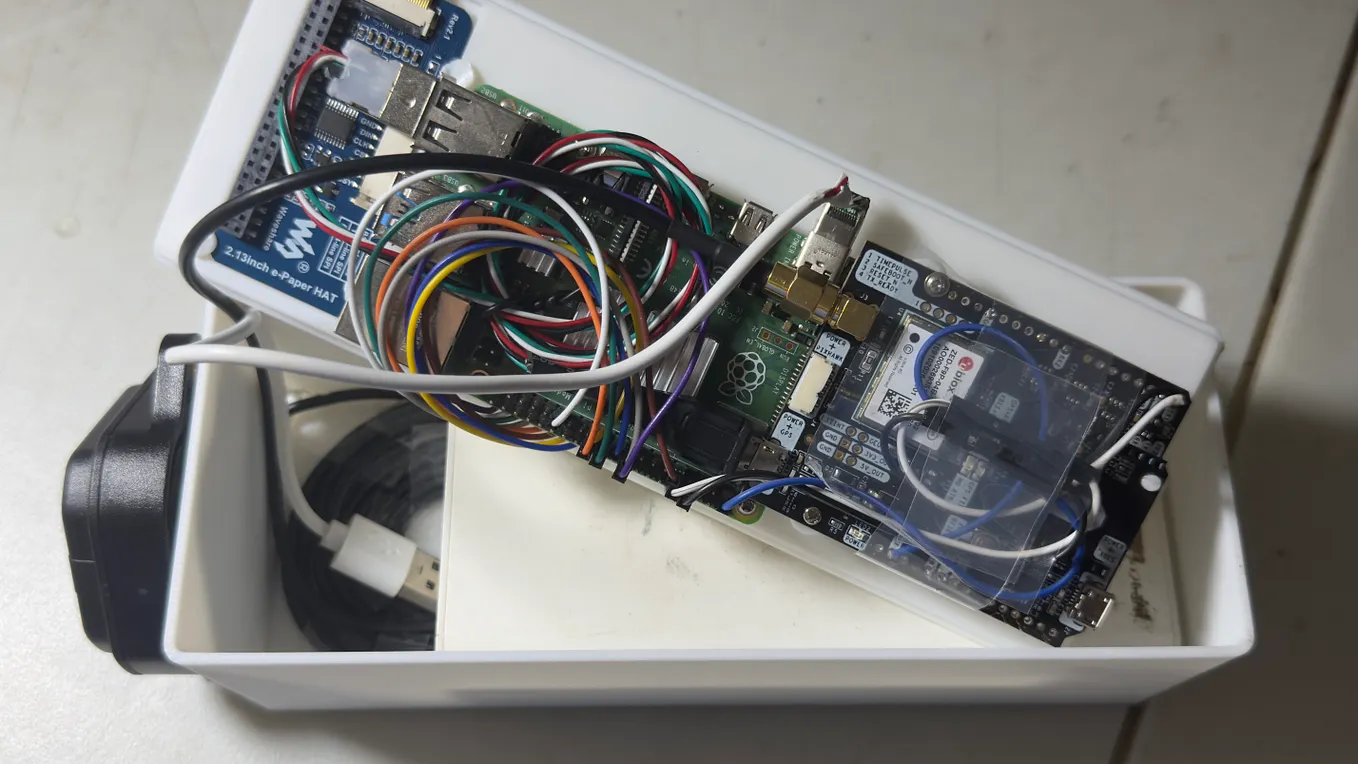
For this reason, I recently added three physical alert mechanisms to my portable RTK tracker:
- A vibration motor
- A high-volume sound alarm
- A bright warning light

After integrating these components into the tracker, I conducted two practical tests. The first tested how the tracker behaves around two separate danger zones. The second recreated an airport ground-safety scenario using a virtual airplane and danger zones around its engines.
Why Use Three Types of Alerts?
Industrial environments can be loud, visually busy, and physically demanding. Relying on only one type of notification creates a weakness.
A sound alert may be difficult to hear near heavy machinery. A warning light may not be visible when the tracker is attached to a worker’s belt or equipment. Vibration alone may be missed during intense physical activity.
By combining sound, light, and vibration, GeoGotar creates a redundant warning system:
- Vibration provides direct physical feedback.
- Sound attracts the attention of the worker and nearby personnel.
- Light provides a visible indication of the active warning.
The objective is to make a danger-zone alert difficult to overlook.
Test One: Two Separate Danger Zones
For the first test, I created two independent danger zones on the map.
I then moved toward each zone while carrying the tracker. The device continuously calculated its RTK position and compared that position with the boundaries of the configured zones.
When the tracker crossed into a danger zone, it activated all three warning mechanisms:
- The vibration motor started.
- The sound alarm activated.
- The warning light turned on.
After leaving the zone, the alert stopped according to the configured system behavior.
I repeated the process with the second danger zone to verify that the tracker was not limited to recognizing only one area. The test demonstrated that the system could independently detect entry into multiple geographically separated zones.
This test validated the complete alert chain:
- Receive the current GNSS/RTK position.
- Compare the position with the configured geofence.
- Detect a boundary crossing.
- Change the tracker’s safety state.
- Activate physical alerts locally on the device.
The most important part is that the alert is generated by the tracker itself. The worker does not need to constantly watch the web interface to know that a boundary has been crossed.
Test Two: Simulating Danger Zones Around an Airplane
For the second test, I wanted to demonstrate how the same technology could be applied to a recognizable industrial safety scenario.
I drew the outline of an airplane on the map and created two danger zones around its engines. I then treated the mapped airplane as though it were a real aircraft parked on an airport apron.
Aircraft engines create serious hazards for ground personnel. The areas near the engine intake and behind the engine can become dangerous while an engine is operating. Depending on the configuration, a positioning system could warn personnel when they approach an engine safety boundary.
For this test, I walked around the simulated aircraft layout with the GeoGotar tracker. As I approached and entered the configured engine danger zones, the tracker detected the boundary crossing and activated its vibration, sound, and light alerts.
This was not a test at an operating airport or near a real aircraft. It was a controlled geofencing demonstration designed to reproduce the geometry and behavior of a possible airport safety use case.
Get Yatsiv Petro’s stories in your inbox
Join Medium for free to get updates from this writer.
The experiment showed how GeoGotar could represent safety areas around complex equipment — not only as simple circles, but as specifically positioned zones associated with individual parts of a machine or vehicle.
From Static Geofencing to Equipment-Aware Safety
The airplane scenario illustrates a larger idea behind GeoGotar.
A danger zone does not always have to represent a fixed location such as a restricted building, excavation area, or hazardous storage site. It can also represent a hazardous area associated with equipment.
Examples could include:
- Engine hazard areas around aircraft
- Blind spots around heavy construction equipment
- Swing-radius zones around excavators
- Operating areas around cranes
- Restricted areas around autonomous vehicles
- Loading and unloading zones
- Temporary maintenance zones
- Areas around moving industrial machinery
In a future implementation, these zones could be attached to the equipment itself. If the equipment changes its position or orientation, its associated danger zones could move and rotate with it.
The zones could also be activated conditionally. For example, an aircraft engine zone could become active only while the engine is operating, or an excavator’s swing zone could activate when the machine begins working.
This transforms geofencing from a collection of static shapes into a dynamic, context-aware safety system.
Why Local Alerts Matter
Cloud monitoring remains an important part of GeoGotar. A supervisor should be able to see worker locations, zone events, positioning quality, and historical movement through the web interface.
However, a safety warning should not depend entirely on an internet connection.
If the tracker already has the required zone information, it can evaluate its position locally and activate the warning immediately. This approach can reduce latency and continue protecting the worker during a temporary LTE or cloud connection failure.
The preferred safety flow is therefore:
Position → Local boundary detection → Immediate physical alert → Cloud event reporting
The worker receives the warning first, while the event can also be transmitted to the GeoGotar platform for supervision, notification, and audit history.
What These Tests Validated
Together, the two tests confirmed several important capabilities:
- The tracker can monitor more than one danger zone.
- It can detect when its position crosses a configured boundary.
- It can activate vibration, sound, and light as a unified warning.
- Alerts can be generated directly on the portable device.
- Geofencing can represent hazards around specific equipment components.
- The same platform can support both general industrial zones and specialized scenarios such as airport ground operations.
These were controlled prototype tests, not a certification of the system for operational aviation use. A production airport deployment would require precise aircraft-specific safety contours, integration with operational status data, extensive reliability testing, human-factors evaluation, and approval from the relevant airport and aviation organizations.
Still, the tests demonstrate the core concept: centimeter-level positioning can do more than display a point on a map. It can help create an immediate connection between a worker’s physical location and the hazards around them.
Next Steps
The next stage is to make the danger-zone logic more dynamic and context-aware.
Planned areas of development include:
- Warning before the worker reaches the critical boundary
- Different alert patterns for warning and critical zones
- Configurable safety margins based on positioning accuracy
- Automatic enlargement of zones when RTK FIX is unavailable
- Dynamic zones that move and rotate with vehicles or equipment
- Event history showing zone entry, exit, and alert duration
- Acknowledgment of alarms by the worker
- Communication of safety events to supervisors in real time
I also plan to test how quickly and consistently the tracker responds when approaching a boundary from different directions and at different movement speeds.